SNVS430I May 2006 – March 2015 LM26001 , LM26001-Q1
PRODUCTION DATA.
- 1 Features
- 2 Applications
- 3 Description
- 4 Revision History
- 5 Pin Configuration and Functions
- 6 Specifications
- 7 Detailed Description
- 8 Applications and Implementation
- 9 Power Supply Recommendations
- 10Layout
- 11Device and Documentation Support
- 12Mechanical, Packaging, and Orderable Information
Package Options
Mechanical Data (Package|Pins)
- PWP|16
Thermal pad, mechanical data (Package|Pins)
- PWP|16
Orderable Information
10 Layout
10.1 Layout Guidelines
Good board layout is critical for switching regulators such as the LM26001. First, the ground plane area must be sufficient for thermal dissipation purposes, and second, appropriate guidelines must be followed to reduce the effects of switching noise.
Switch mode converters are very fast switching devices. In such devices, the rapid increase of input current combined with parasitic trace inductance generates unwanted Ldi/dt noise spikes at the SW node and also at the VIN node. The magnitude of this noise tends to increase as the output current increases. This parasitic spike noise may turn into electromagnetic interference (EMI), and can also cause problems in device performance. Therefore, care must be taken in layout to minimize the effect of this switching noise.
The current sensing circuit in current mode devices can be easily affected by switching noise. This noise can cause duty cycle jitter which leads to increased spectral noise. Although the LM26001 has 100ns blanking time at the beginning of every cycle to ignore this noise, some noise may remain after the blanking time. Following the important guidelines below will help minimize switching noise and its effect on current sensing.
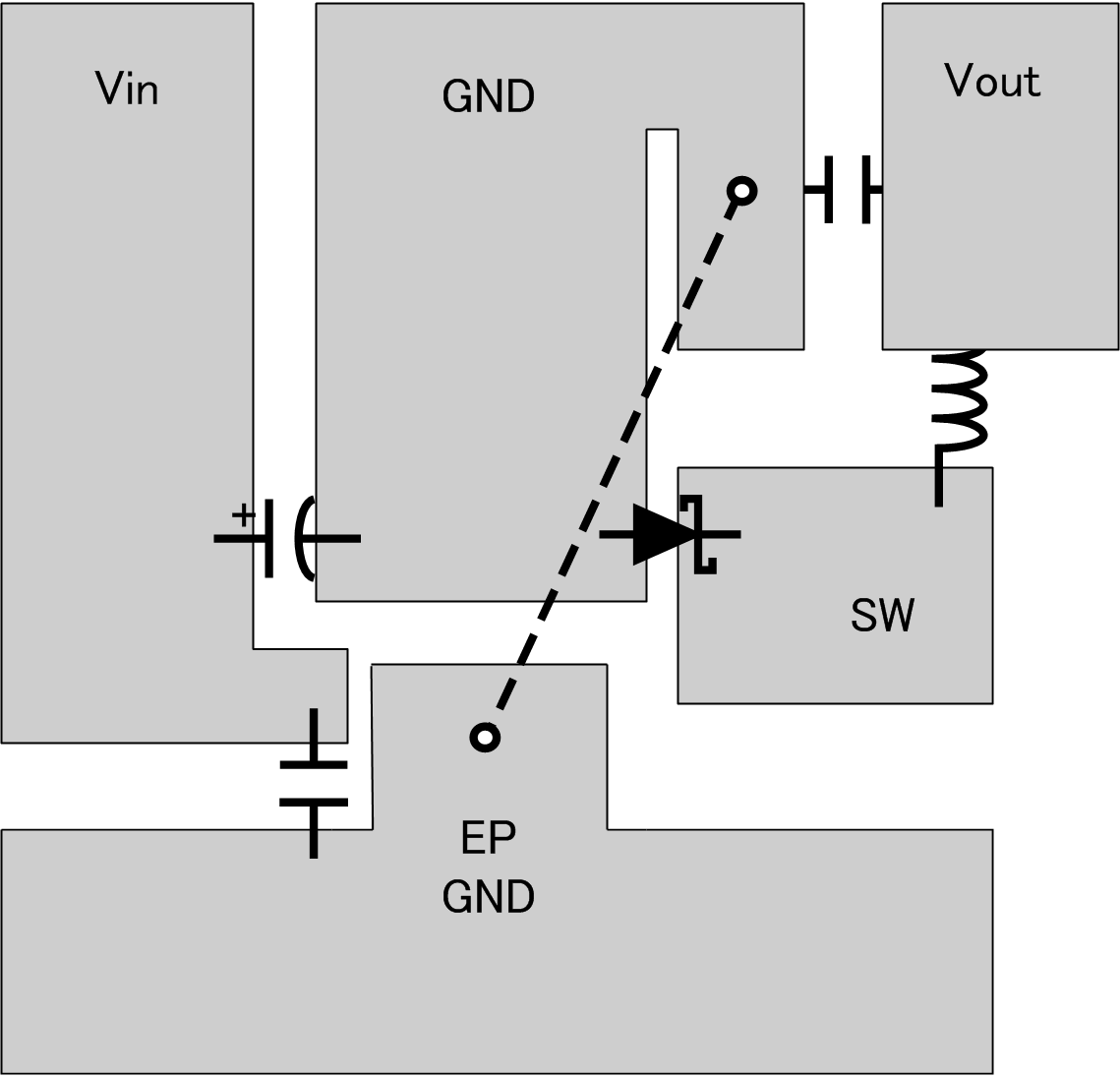
The switch node area should be as small as possible. The catch diode, input capacitors, and output capacitors should be grounded to a large ground plane, with the bulk input capacitor grounded as close as possible to the catch diode anode. Additionally, the ground area between the catch diode and bulk input capacitor is very noisy and should be somewhat isolated from the rest of the ground plane.
A ceramic input capacitor must be connected as close as possible to the VIN pin and grounded close to the GND pin. Often this capacitor is most easily located on the bottom side of the pcb. If placement close to the GND pin is not practical, the ceramic input capacitor can also be grounded close to the catch diode ground. The above layout recommendations are illustrated below in Figure 26.
It is a good practice to connect the EP, GND pin, and small signal components (COMP, FB, FREQ) to a separate ground plane, shown in Figure 26 as EP GND, and in the schematics as a signal ground symbol. Both the exposed pad and the GND pin must be connected to ground. This quieter plane should be connected to the high current ground plane at a quiet location, preferably near the Vout ground as shown by the dashed line in Figure 26.
The EP GND plane should be made as large as possible, since it is also used for thermal dissipation. Several vias can be placed directly below the EP to increase heat flow to other layers when they are available. The recommended via hole diameter is 0.3mm.
The trace from the FB pin to the resistor divider should be short and the entire feedback trace must be kept away from the inductor and switch node. See AN-1229 SIMPLE SWITCHER® PCB Layout Guidelines, SNVA054, for more information regarding PCB layout for switching regulators.
10.2 Layout Example
 Figure 26. Example PCB Layout
10.3 Thermal Considerations and TSD
Although the LM26001 has a built in current limit, at ambient temperatures above 80°C, device temperature rise may limit the actual maximum load current. Therefore, temperature rise must be taken into consideration to determine the maximum allowable load current.
Temperature rise is a function of the power dissipation within the device. The following equations can be used to calculate power dissipation (PD) and temperature rise, where total PD is the sum of FET switching losses, FET DC losses, drive losses, Iq, and VBIAS losses:

Given this total power dissipation, junction temperature can be calculated as follows:
Where θJA=38°C/W (typically) when using a multi-layer board with a large copper plane area. θJA varies with board type and metallization area.
To calculate the maximum allowable power dissipation, assume Tj = 125°C. To ensure that junction temperature does not exceed the maximum operating rating of 125°C, power dissipation should be verified at the maximum expected operating frequency, maximum ambient temperature, and minimum and maximum input voltage. The calculated maximum load current is based on continuous operation and may be exceeded during transient conditions.
If the power dissipation remains above the maximum allowable level, device temperature will continue to rise. When the junction temperature exceeds its maximum, the LM26001 engages Thermal Shut Down (TSD). In TSD, the part remains in a shutdown state until the junction temperature falls to within normal operating limits. At this point, the device restarts in soft-start mode.