SNVS052E September 1999 – April 2016 LM809 , LM810
PRODUCTION DATA.
- 1 Features
- 2 Applications
- 3 Description
- 4 Revision History
- 5 Pin Configuration and Functions
- 6 Specifications
- 7 Detailed Description
- 8 Application and Implementation
- 9 Power Supply Recommendations
- 10Layout
- 11Device and Documentation Support
- 12Mechanical, Packaging, and Orderable Information
Package Options
Mechanical Data (Package|Pins)
- DBZ|3
Thermal pad, mechanical data (Package|Pins)
Orderable Information
7 Detailed Description
7.1 Overview
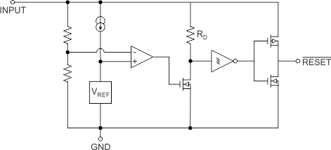
The LM809 and LM810 microprocessor supervisory circuits provide a simple solution to monitor the power supplies in microprocessor and digital systems and provide a reset during power-up, power-down, and brown-out conditions. The reset signal is controlled by the factory-programmed reset threshold on the VCC supply voltage pin. When the voltage declines below the reset threshold, the reset signal is asserted and remains asserted for 240 ms after VCC rises above the threshold. The LM809 has an active-low RESET output, while the LM810 has an active-high RESET output. The available threshold options are 2.63 V, 2.93 V, 3.08 V, 4.38 V, and 4.63 V to provide precision monitoring of supply voltages.
7.2 Functional Block Diagram

7.3 Feature Description
7.3.1 Benefits of Precision Reset Thresholds
A microprocessor supply supervisor must provide a reset output within a predictable range of the supply voltage. A common threshold range is between 5% and 10% below the nominal supply voltage. The 4.63-V and 3.08-V options of the LM809 and LM810 use highly accurate circuitry to ensure that the reset threshold occurs only within this range (for 5-V and 3.3-V supplies). The other voltage options have the same tight tolerance to ensure a reset signal for other narrow monitor ranges. See Table 1 for examples of how the standard reset thresholds apply to 3-V, 3.3-V, and 5-V nominal supply voltages.
Table 1. Reset Thresholds Related to Common Supply Voltages
| Reset Threshold | 3 V | 3.3 V | 5 V |
|---|---|---|---|
| 4.63 ± 3% | 90 – 95% | ||
| 4.38 ± 3% | 85 – 90% | ||
| 4.00 ± 3% | 78 – 82% | ||
| 3.08 ± 3% | 90 – 95% | ||
| 2.93 ± 3% | 86 – 90% | ||
| 2.63 ± 3% | 85 – 90% | 77 – 81% | |
| 2.45 ± 3% | 79 – 84% | 72 – 76% |
7.3.1.1 Ensuring a Valid Reset Output Down to VCC = 0 V
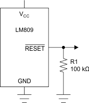
When VCC falls below 1 V, the LM809 RESET output no longer sinks current. A high-impedance CMOS logic input connected to RESET can therefore drift to undetermined voltages. To prevent this situation, a 100-kΩ resistor should be connected from the RESET output to ground, as shown in Figure 7.
A 100-kΩ pullup resistor to VCC is also recommended for the LM810, if RESET is required to remain valid for VCC < 1 V.
 Figure 7. RESET Valid to VCC = Ground Circuit
7.3.1.2 Negative-Going VCC Transients
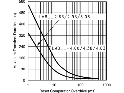
The LM809 and LM810 are relatively immune to short negative-going transients or glitches on VCC. Figure 8 shows the maximum pulse width a negative-going VCC transient can have without causing a reset pulse. In general, as the magnitude of the transient increases, going further below the threshold, the maximum allowable pulse width decreases. Typically, for the 4.63-V and 4.38-V version of the LM809 or LM810, a VCC transient that goes 100 mV below the reset threshold and lasts 20 µs or less will not cause a reset pulse. A 0.1-µF bypass capacitor mounted as close as possible to the VCC pin will provide additional transient rejection.
 Figure 8. Maximum Transient Duration without Causing a Reset Pulse vs Reset Comparator Overdrive
7.3.1.3 Interfacing to µPs with Bidirectional Reset Pins
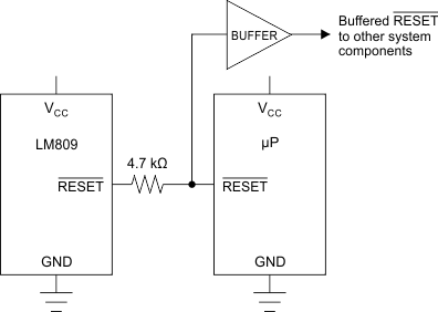
Microprocessors with bidirectional reset pins, such as the Motorola 68HC11 series, can be connected to the LM809 RESET output. To ensure a correct output on the LM809 even when the microprocessor reset pin is in the opposite state, connect a 4.7-kΩ resistor between the LM809 RESET output and the µP reset pin, as shown in Figure 9. Buffer the LM809 RESET output to other system components.
 Figure 9. Interfacing to Microprocessors with Bidirectional Reset I/O
7.4 Device Functional Modes
7.4.1 VCC Supply Voltage Low
When VCC supply voltage declines below the reset threshold, the RESET output is asserted. For LM809, the active-low RESET output is low. For LM810, the active-high RESET output is high.
7.4.2 VCC Supply Voltage High
When the VCC supply voltage rises above the reset threshold, the RESET output resets after 240 ms. For LM809, the active-low RESET output rises high. For LM810, the active-high RESET output drops low.