SBOS997 August 2020 – MONTH LMH9135
PRODUCTION DATA
- 1 Features
- 2 Applications
- 3 Description
- 4 Revision History
- 5 Pin Configuration and Functions
- 6 Specifications
- 7 Detailed Description
- 8 Application and Implementation
- 9 Power Supply Recommendations
- 10Layout
- 11Device and Documentation Support
- 12Mechanical, Packaging, and Orderable Information
Package Options
Mechanical Data (Package|Pins)
- RRL|12
Thermal pad, mechanical data (Package|Pins)
Orderable Information
8.2 Typical Application
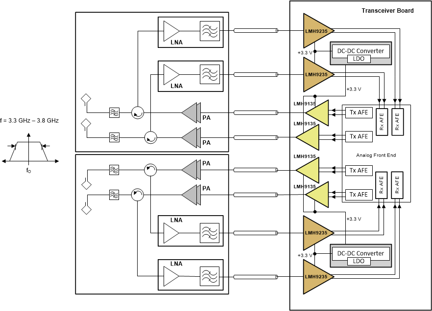
LMH9135 is typically used in a four transmit and four receive (4T/4R) array of active antenna system for 5G, TDD, wireless base station applications. Such a system is shown in Figure 8-1, where the LMH9135 is used in the transmit path as an active balun that converts differential DAC output from Tx AFE to single-ended signal. Also shown in the figure is the application of LMH9235 chip, which is the counter-part of LMH9135 in the Receive path.
 Figure 8-1 LMH9135 in a 4T/4R 5G Active Antenna System
The 4T/4R system can be scaled to 16T/16R, 64T/64R, or higher antenna arrays that result in proportional scaling of the overall system power dissipation. As a result of the proportional scaling factor for multiple channels in a system, the individual device power consumption must be reduced to dissipate less overall heat in the system. Operating on a single 3.3-V supply, the LMH9135 consumes only about 400 mW and therefore provides power saving to the customer. Multiple LMH9135 devices can be powered from a single DC/DC converter or a low-dropout regulator (LDO) operating on a 3.3-V supply. A DC/DC converter provides the most power efficient way of generating the 3.3-V supply. However, care must be taken when using the DC/DC converter to minimize the switching noise using inductor chokes and adequate isolation must be provided between the analog and digital power domains.