SLIS136C September 2011 – September 2019 TPL0501-100
PRODUCTION DATA.
- 1 Features
- 2 Applications
- 3 Description
- 4 Revision History
- 5 Pin Configuration and Functions
- 6 Specifications
- 7 Detailed Description
- 8 Application and Implementation
- 9 Power Supply Recommendations
- 10Layout
- 11Device and Documentation Support
- 12Mechanical, Packaging, and Orderable Information
Package Options
Mechanical Data (Package|Pins)
Thermal pad, mechanical data (Package|Pins)
- DCN|8
Orderable Information
7.4.2 Rheostat Mode
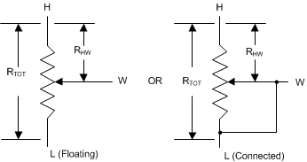
The TPL0501 operates in rheostat mode when only two terminals are used as a variable resistor. The variable resistance can either be between terminal H and terminal W or between terminal L and terminal W. The unused terminal can be left floating or it can be tied to terminal W. The nominal resistance between terminal H and terminal L is 10 kΩ and has 256 tap points accessed by the wiper terminal. The 8-bit volatile register value is used to determine one of the 256 possible wiper positions.
To set the resistance between terminal H and terminal W in rheostat mode, the potentiometer can be configured in two possible ways (see Figure 13).
 Figure 13. Equivalent Circuit for Rheostat Mode With Terminal H to Terminal W Resistance
 The general equation for determining the digitally programmed output resistance between Terminal H and Terminal W is Equation 3:

where
- RTOT is the end-to-end resistance between terminal H and terminal L.
- D is the decimal value of the wiper code
Similarly, to set the resistance between terminal L and terminal W, the potentiometer can be configured in two possible ways.
 Figure 14. Equivalent Circuit for Rheostat Mode With Terminal L to Terminal W Resistance
 The general equation for determining the digitally programmed output resistance between terminal L and terminal W is Equation 4:

where
- RTOT is the end-to-end resistance between terminal H and terminal L
- D is the decimal value of the wiper code.