SNAS628B JULY 2013 – December 2014 TPL5000
PRODUCTION DATA.
- 1 Features
- 2 Applications
- 3 Description
- 4 Simplified Application Schematic
- 5 Revision History
- 6 Pin Configuration and Functions
- 7 Specifications
- 8 Detailed Description
- 9 Application and Implementation
- 10Power Supply Recommendations
- 11Layout
- 12Device and Documentation Support
- 13Mechanical, Packaging, and Orderable Information
Package Options
Mechanical Data (Package|Pins)
- DGS|10
Thermal pad, mechanical data (Package|Pins)
Orderable Information
9 Application and Implementation
NOTE
Information in the following applications sections is not part of the TI component specification, and TI does not warrant its accuracy or completeness. TI’s customers are responsible for determining suitability of components for their purposes. Customers should validate and test their design implementation to confirm system functionality.
9.1 Application Information
In battery powered applications the design of the system is driven by low current consumption. The TPL5000 is suitable in the applications where there is the needs to monitor environment conditions at fixed timer interval. Often in these applications the micro is kept on to enable the watchdog and to count the elapsed time. Some time due to the high frequency clock of the micro controllers special structure needs to be configured to count for long time (several seconds). The TPL5000 can do the same job burning only tens of nA.
9.2 Typical Application
The TPL5000 can be used in conjunction with environment sensors to build a low-power environment data-logger, such as an air quality data-logger. In this application due to the monitored phenomena the micro-controller and the front end of the sensor spend most of the time in idle state, waiting for the next working interval, usually few hundred of ms. The application is based on a micro-controller which represents the core of the data-logger, a front end for gas sensor, such as the LMP91000.
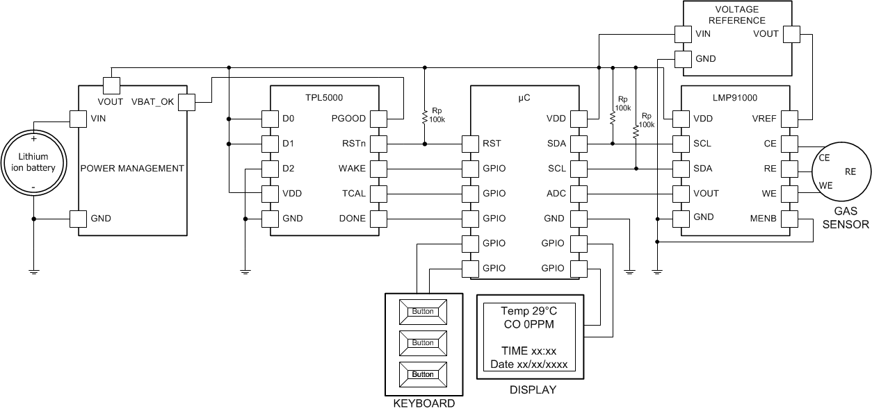 Figure 8. Data-logger
9.2.1 Design Requirements
The design is driven by the low current consumption constraint. The data are usually acquired on a rate that ranges between 1 s to 10 s. The highest necessity it the maximization of the battery life. The TPL5000 helps achieve that goal because it allows putting the micro-controller in its lowest power mode.
9.2.2 Detailed Design Procedure
When the focal constraint is the battery, the selection of a low power voltage reference, a micro-controller and display is mandatory. The first step in the design is the calculation of the power consumption of each device in the different mode of operations. An example is the LMP91000; the device has gas measurement mode, sleep mode and micro-controller in low-power mode which is normal operation. The different modes offer the possibility to select the appropriate timer interval which respect the application constraint and maximize the life of the battery.
9.2.3 Application Curve
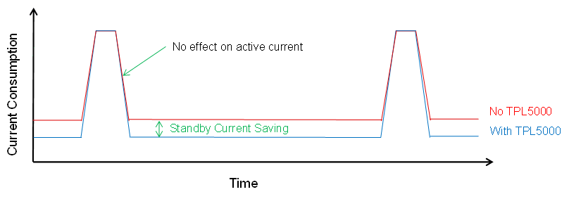 Figure 9. Effect of TPL5000 on Current Consumption