SLDS251A December 2019 – May 2022 TUSS4470
PRODUCTION DATA
- 1 Features
- 2 Applications
- 3 Description
- 4 Revision History
- 5 Pin Configuration and Functions
-
6 Specifications
- 6.1 Absolute Maximum Ratings
- 6.2 ESD Ratings
- 6.3 Recommended Operating Conditions
- 6.4 Thermal Information
- 6.5 Power-Up Characteristics
- 6.6 Transducer Drive
- 6.7 Receiver Characteristics
- 6.8 Echo Interrupt Comparator Characteristics
- 6.9 Digital I/O Characteristics
- 6.10 Switching Characteristics
- 6.11 Typical Characteristics
- 7 Detailed Description
- 8 Application and Implementation
- 9 Power Supply Recommendations
- 10Layout
- 11Device and Documentation Support
- 12Mechanical, Packaging, and Orderable Information
Package Options
Mechanical Data (Package|Pins)
- RTJ|20
Thermal pad, mechanical data (Package|Pins)
- RTJ|20
Orderable Information
8.2.1.2.2 Transducer Driving Frequency
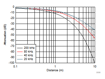
The strength of ultrasonic waves propagated into the air attenuate proportionally with distance. This attenuation is caused by diffusion, diffraction, and absorption loss as the ultrasonic energy transmits through the medium of air. As shown in Figure 8-3, the higher the frequency of the ultrasonic wave, the larger the attenuation rate and the shorter the distance the wave reaches.
 Figure 8-3 Attenuation Characteristics of Sound Pressure by Distance
An ultrasonic transducer has a fixed resonant center frequency with a typical tolerance of ±2%. The lower frequency range of 30 kHz to 100 kHz is the default operating range for common long range applications for a step resolution of 1 cm and typical range of 30 cm to 5 m. The upper frequency range of 100 kHz to 1000 kHz is reserved for high-precision applications with a step resolution of 1 mm and a typical range of 5 cm to 1 m.