SLDS251A December 2019 – May 2022 TUSS4470
PRODUCTION DATA
- 1 Features
- 2 Applications
- 3 Description
- 4 Revision History
- 5 Pin Configuration and Functions
-
6 Specifications
- 6.1 Absolute Maximum Ratings
- 6.2 ESD Ratings
- 6.3 Recommended Operating Conditions
- 6.4 Thermal Information
- 6.5 Power-Up Characteristics
- 6.6 Transducer Drive
- 6.7 Receiver Characteristics
- 6.8 Echo Interrupt Comparator Characteristics
- 6.9 Digital I/O Characteristics
- 6.10 Switching Characteristics
- 6.11 Typical Characteristics
- 7 Detailed Description
- 8 Application and Implementation
- 9 Power Supply Recommendations
- 10Layout
- 11Device and Documentation Support
- 12Mechanical, Packaging, and Orderable Information
Package Options
Mechanical Data (Package|Pins)
- RTJ|20
Thermal pad, mechanical data (Package|Pins)
- RTJ|20
Orderable Information
3 Description
The TUSS4470 is a highly integrated direct drive analog front end for industrial ultrasonic applications. The transducer drive stage is an internal H-bridge that can be configured to drive the transducer in direct-drive mode to achieve maximum voltage across the transducer. The internal H-bridge can also be configured as a pre-driver for external FETs, enabling higher current and voltage drive for larger transducers.
The receive signal path includes a low-noise linear amplifier, a bandpass filter, followed by a logarithmic gain amplifier for input dependent amplification. The logarithmic amplifier allows for high sensitivity for weak echo signals and offers excellent input dynamic range over full range of reflected echoes.
The drivers can be controlled directly through the microcontroller for complete customization of the burst signal, or can be programmed through SPI with a customizable burst length. The TUSS4470 can support a single transducer to send and receive burst signals, or can set up two transducers to split the send and receive functions.
| PART NUMBER | PACKAGE | BODY SIZE (NOM) |
|---|---|---|
| TUSS4470 | WQFN (20) | 4.00 mm × 4.00 mm |
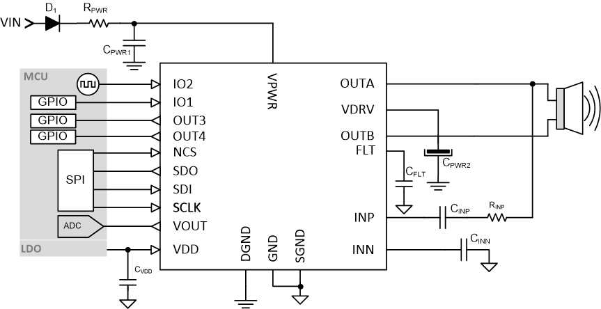
 TUSS4470 Application Diagram