JAJSJH4D december 2010 – september 2020 BQ24133
PRODUCTION DATA
- 1
- 1 特長
- 2 アプリケーション
- 3 概要
- 4 Revision History
- 5 Description (continued)
- 6 Device Comparison Table
- 7 Pin Configuration and Functions
- 8 Specifications
-
9 Detailed Description
- 9.1 Overview
- 9.2 Functional Block Diagram
- 9.3
Feature Description
- 9.3.1 Battery Voltage Regulation
- 9.3.2 Battery Current Regulation
- 9.3.3 Battery Precharge Current Regulation
- 9.3.4 Input Current Regulation
- 9.3.5 Charge Termination, Recharge, And Safety Timers
- 9.3.6 Power Up
- 9.3.7 Input Undervoltage Lockout (UVLO)
- 9.3.8 Input Overvoltage/Undervoltage Protection
- 9.3.9 Enable and Disable Charging
- 9.3.10 System Power Selector
- 9.3.11 Converter Operation
- 9.3.12 Automatic Internal Soft-Start Charger Current
- 9.3.13 Charge Overcurrent Protection
- 9.3.14 Charge Undercurrent Protection
- 9.3.15 Battery Detection
- 9.3.16 Battery Short Protection
- 9.3.17 Battery Overvoltage Protection
- 9.3.18 Temperature Qualification
- 9.3.19 MOSFET Short Circuit and Inductor Short Circuit Protection
- 9.3.20 Thermal Regulation and Shutdown Protection
- 9.3.21 Timer Fault Recovery
- 9.3.22 Charge Status Outputs
- 9.4 Device Functional Modes
- 10Application and Implementation
- 11Power Supply Recommendations
- 12Layout
- 13Device and Documentation Support
- 14Mechanical, Packaging, and Orderable Information
パッケージ・オプション
メカニカル・データ(パッケージ|ピン)
- RGY|24
サーマルパッド・メカニカル・データ
- RGY|24
発注情報
9.3.15 Battery Detection
For applications with removable battery packs, IC provides a battery absent detection scheme to reliably detect insertion or removal of battery packs. The battery detection routine runs on power up, or if battery voltage falls below recharge threshold voltage due to removing a battery or discharging a battery.
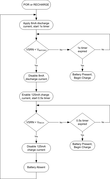
 Figure 9-2 Battery Detection Flow Chart
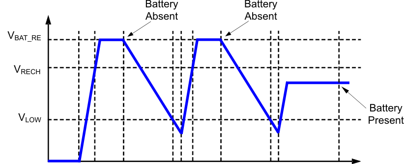
Once the device has powered up, an 8-mA discharge current is applied to the SRN terminal. If the battery voltage falls below the LOWV threshold within 1 second, the discharge source is turned off, and the charger is turned on at low charge current (125 mA). If the battery voltage gets up above the recharge threshold within 500 ms, there is no battery present and the cycle restarts. If either the 500 ms or 1 second timer times out before the respective thresholds are hit, a battery is detected and a charge cycle is initiated.
 Figure 9-3 Battery Detect Timing Diagram
Ensure that the total output capacitance at the battery node is not so large that the discharge current source cannot pull the voltage below the LOWV threshold during the 1 second discharge time. The maximum output capacitances can be calculated according to the following equations:

where
- CMAX is the maximum output capacitance.
- IDISCH is the discharge current.
- tDISCH is the discharge time.