JAJSJH4D december 2010 – september 2020 BQ24133
PRODUCTION DATA
- 1
- 1 特長
- 2 アプリケーション
- 3 概要
- 4 Revision History
- 5 Description (continued)
- 6 Device Comparison Table
- 7 Pin Configuration and Functions
- 8 Specifications
-
9 Detailed Description
- 9.1 Overview
- 9.2 Functional Block Diagram
- 9.3
Feature Description
- 9.3.1 Battery Voltage Regulation
- 9.3.2 Battery Current Regulation
- 9.3.3 Battery Precharge Current Regulation
- 9.3.4 Input Current Regulation
- 9.3.5 Charge Termination, Recharge, And Safety Timers
- 9.3.6 Power Up
- 9.3.7 Input Undervoltage Lockout (UVLO)
- 9.3.8 Input Overvoltage/Undervoltage Protection
- 9.3.9 Enable and Disable Charging
- 9.3.10 System Power Selector
- 9.3.11 Converter Operation
- 9.3.12 Automatic Internal Soft-Start Charger Current
- 9.3.13 Charge Overcurrent Protection
- 9.3.14 Charge Undercurrent Protection
- 9.3.15 Battery Detection
- 9.3.16 Battery Short Protection
- 9.3.17 Battery Overvoltage Protection
- 9.3.18 Temperature Qualification
- 9.3.19 MOSFET Short Circuit and Inductor Short Circuit Protection
- 9.3.20 Thermal Regulation and Shutdown Protection
- 9.3.21 Timer Fault Recovery
- 9.3.22 Charge Status Outputs
- 9.4 Device Functional Modes
- 10Application and Implementation
- 11Power Supply Recommendations
- 12Layout
- 13Device and Documentation Support
- 14Mechanical, Packaging, and Orderable Information
パッケージ・オプション
メカニカル・データ(パッケージ|ピン)
- RGY|24
サーマルパッド・メカニカル・データ
- RGY|24
発注情報
3 概要
BQ24133 は 2 つの N チャネル・パワー MOSFET を内蔵しており、高集積でスタンドアロンのリチウム・イオン / リチウム・ポリマ切り換えモード・バッテリ充電器として動作します。入力電流、充電電流、電圧の高精度レギュレーションを行う固定周波数同期整流式 PWM コントローラを提供します。BQ24133 はバッテリ・パックの温度を厳密に監視し、プリセットされた温度ウィンドウのみでの充電を可能にします。BQ24133 は、セルあたり 4.2V 固定で、1 セル、2 セル、または 3 セル (CELL ピンで選択) を充電します。
製品情報(1)
| 部品番号 | パッケージ | 本体サイズ (公称) |
|---|---|---|
| BQ24133 | VQFN (24) | 5.50mm × 3.50mm |
(1) 利用可能なすべてのパッケージについては、データシートの末尾にある注文情報を参照してください。
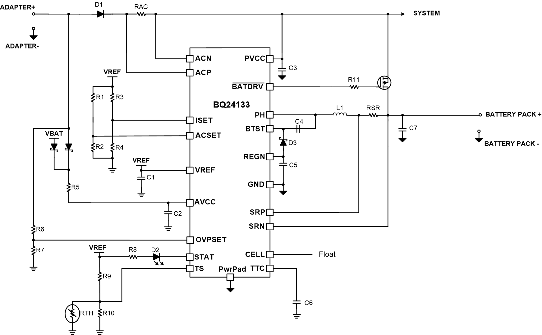
 代表的なアプリケーション回路図