JAJSFX6C August 2018 – July 2019 INA821
PRODUCTION DATA.
- 1 特長
- 2 アプリケーション
- 3 概要
- 4 改訂履歴
- 5 Device Comparison Table
- 6 Pin Configuration and Functions
- 7 Specifications
- 8 Detailed Description
- 9 Application and Implementation
- 10Power Supply Recommendations
- 11Layout
- 12デバイスおよびドキュメントのサポート
- 13メカニカル、パッケージ、および注文情報
パッケージ・オプション
メカニカル・データ(パッケージ|ピン)
サーマルパッド・メカニカル・データ
- DRG|8
発注情報
9.3.1 Resistance Temperature Detector Interface
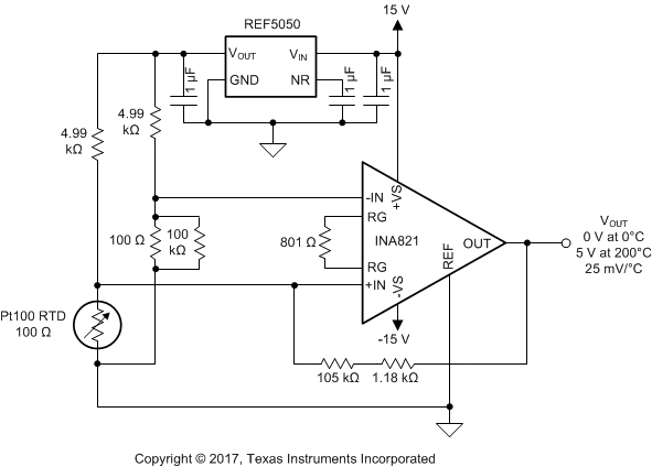
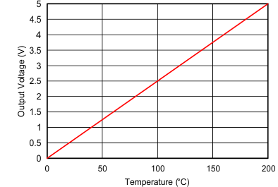
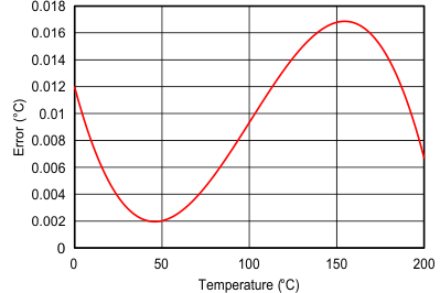
Figure 72 illustrates a 3-wire interface circuit for resistance temperature detectors (RTDs). The circuit incorporates analog linearization and has an output voltage range from 0 V to 5 V. The linearization technique employed is described in Analog linearization of resistance temperature detectors analog application journal. Series and parallel combinations of standard 1% resistor values are used to achieve less than 0.02°C of error over a 200°C temperature span.
 Figure 72. A 3-Wire Interface for RTDs With Analog Linearization
  Figure 73. Transfer Function of 3-Wire RTD Interface
  Figure 74. Temperature Error Over Full Temperature Range