JAJSL67A June   2021  – February 2023 LM25148-Q1

PRODUCTION DATA  

  1. 特長
  2. アプリケーション
  3. 概要
  4. Revision History
  5. 概要 (続き)
  6. Pin Configuration and Functions
    1. 6.1 Wettable Flanks
  7. Specifications
    1. 7.1 Absolute Maximum Ratings
    2. 7.2 ESD Ratings 
    3. 7.3 Recommended Operating Conditions
    4. 7.4 Thermal Information
    5. 7.5 Electrical Characteristics
    6. 7.6 Typical Characteristics
  8. Detailed Description
    1. 8.1 Overview
    2. 8.2 Functional Block Diagram
    3. 8.3 Feature Description
      1. 8.3.1  Input Voltage Range (VIN)
      2. 8.3.2  High-Voltage Bias Supply Regulator (VCC, VCCX, VDDA)
      3. 8.3.3  Precision Enable (EN)
      4. 8.3.4  Power-Good Monitor (PG)
      5. 8.3.5  Switching Frequency (RT)
      6. 8.3.6  Dual Random Spread Spectrum (DRSS)
      7. 8.3.7  Soft Start
      8. 8.3.8  Output Voltage Setpoint (FB)
      9. 8.3.9  Minimum Controllable On Time
      10. 8.3.10 Error Amplifier and PWM Comparator (FB, EXTCOMP)
      11. 8.3.11 Slope Compensation
      12. 8.3.12 Inductor Current Sense (ISNS+, VOUT)
        1. 8.3.12.1 Shunt Current Sensing
        2. 8.3.12.2 Inductor DCR Current Sensing
      13. 8.3.13 Hiccup Mode Current Limiting
      14. 8.3.14 High-Side and Low-Side Gate Drivers (HO, LO)
      15. 8.3.15 Output Configurations (CNFG)
      16. 8.3.16 Single-Output Dual-Phase Operation
    4. 8.4 Device Functional Modes
      1. 8.4.1 Sleep Mode
      2. 8.4.2 Pulse Frequency Modulation and Synchronization (PFM/SYNC)
      3. 8.4.3 Thermal Shutdown
  9. Application and Implementation
    1. 9.1 Application Information
      1. 9.1.1 Power Train Components
        1. 9.1.1.1 Buck Inductor
        2. 9.1.1.2 Output Capacitors
        3. 9.1.1.3 Input Capacitors
        4. 9.1.1.4 Power MOSFETs
        5. 9.1.1.5 EMI Filter
      2. 9.1.2 Error Amplifier and Compensation
    2. 9.2 Typical Applications
      1. 9.2.1 Design 1 – High Efficiency 2.1-MHz Synchronous Buck Regulator
        1. 9.2.1.1 Design Requirements
        2. 9.2.1.2 Detailed Design Procedure
          1. 9.2.1.2.1 Custom Design with WEBENCH® Tools
          2. 9.2.1.2.2 Buck Inductor
          3. 9.2.1.2.3 Current-Sense Resistance
          4. 9.2.1.2.4 Output Capacitors
          5. 9.2.1.2.5 Input Capacitors
          6. 9.2.1.2.6 Frequency Set Resistor
          7. 9.2.1.2.7 Feedback Resistors
          8. 9.2.1.2.8 Compensation Components
        3. 9.2.1.3 Application Curves
      2. 9.2.2 Design 2 – High Efficiency 440-kHz Synchronous Buck Regulator
        1. 9.2.2.1 Design Requirements
        2. 9.2.2.2 Detailed Design Procedure
        3. 9.2.2.3 Application Curves
      3. 9.2.3 Design 3 – Dual-Phase 400-kHz 20-A Synchronous Buck Regulator
        1. 9.2.3.1 Design Requirements
        2. 9.2.3.2 Detailed Design Procedure
        3. 9.2.3.3 Application Curves
    3. 9.3 Power Supply Recommendations
    4. 9.4 Layout
      1. 9.4.1 Layout Guidelines
        1. 9.4.1.1 Power Stage Layout
        2. 9.4.1.2 Gate-Drive Layout
        3. 9.4.1.3 PWM Controller Layout
        4. 9.4.1.4 Thermal Design and Layout
        5. 9.4.1.5 Ground Plane Design
      2. 9.4.2 Layout Example
  10. 10Device and Documentation Support
    1. 10.1 Device Support
      1. 10.1.1 Development Support
        1. 10.1.1.1 Custom Design with WEBENCH® Tools
    2. 10.2 Documentation Support
      1. 10.2.1 Related Documentation
        1. 10.2.1.1 PCB Layout Resources
        2. 10.2.1.2 Thermal Design Resources
    3. 10.3 ドキュメントの更新通知を受け取る方法
    4. 10.4 サポート・リソース
    5. 10.5 Trademarks
    6. 10.6 静電気放電に関する注意事項
    7. 10.7 用語集
  11. 11Mechanical, Packaging, and Orderable Information

パッケージ・オプション

メカニカル・データ(パッケージ|ピン)
サーマルパッド・メカニカル・データ
発注情報

Error Amplifier and Compensation

Figure 9-3 shows a type-ll compensator using a transconductance error amplifier (EA). The dominant pole of the EA open-loop gain is set by the EA output resistance, RO-EA, and effective bandwidth-limiting capacitance, CBW, as shown by Equation 26.

Equation 26. GUID-630B357C-1D16-462A-82D2-34EE47660A07-low.gif

The EA high-frequency pole is neglected in the above expression. Equation 27 calculates the compensator transfer function from output voltage to COMP node, including the gain contribution from the (internal or external) feedback resistor network.

Equation 27. GUID-E78E6CC3-93FF-4171-A4F9-54EE0B2945C9-low.gif

where

  • VREF is the feedback voltage reference of 0.8 V.
  • gm is the EA gain transconductance of 1200 µS.
  • RO-EA is the error amplifier output impedance of 64 MΩ.
Equation 28. GUID-43A9FEBA-A4B9-4D83-B44D-C39CC7BB8ECE-low.gif
Equation 29. GUID-4B840B00-3631-46B9-A834-F36A1D812BB0-low.gif
Equation 30. GUID-81F5F67B-9800-4BED-9D4B-8EEECCDB3600-low.gif

The EA compensation components create a pole close to the origin, a zero, and a high-frequency pole. Typically, RCOMP << RO-EA and CCOMP >> CBW and CHF, so the approximations are valid.
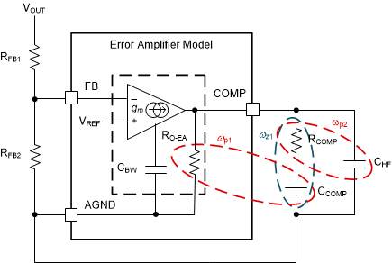
GUID-00B8E82F-057A-4B0F-A293-510D7AD79615-low.gifFigure 9-3 Error Amplifier and Compensation Network