SNVS457D February 2007 – October 2015 LM26400Y
PRODUCTION DATA.
8 Application and Implementation
NOTE
Information in the following applications sections is not part of the TI component specification, and TI does not warrant its accuracy or completeness. TI’s customers are responsible for determining suitability of components for their purposes. Customers should validate and test their design implementation to confirm system functionality.
8.1 Application Information
The LM26400Y device will operate with input voltage from 3 V to 20 V and provide two regulated output voltages. The device is optimized for high-efficiency operation with minimum number of external components.
8.2 Typical Applications
8.2.1 LM26400Y Design Example 1
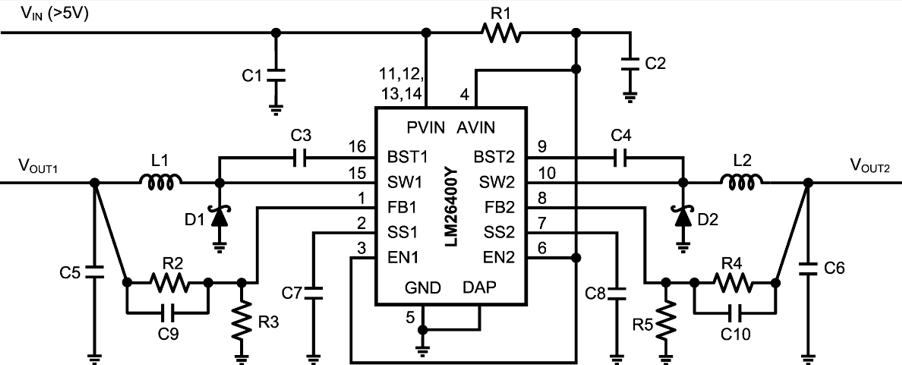
8.2.1.1 Design Requirements
The device must be able to operate at any voltage within the recommended operating range. The load current must be defined in order to properly size the inductor, input, and output capacitors .The inductor must be able to handle full expected load current as well as the peak current generated load transients and start-up.
8.2.1.2 Detailed Design Procedure
The best capacitors for use with the LM26400Y are multi-layer ceramic capacitors. They have the lowest ESR (equivalent series resistance) and highest resonance frequency which makes them optimum for use with high frequency switching converters. When selecting a ceramic capacitor, only X5R and X7R dielectric types should be used. Other types such as Z5U and Y5F have such severe loss of capacitance due to effects of temperature variation and applied voltage, they may provide as little as 20% of rated capacitance in many typical applications. Always consult capacitor manufacturer’s data curves before selecting a capacitor. High-quality ceramic capacitors can be obtained from Taiyo-Yuden, AVX, and Murata.
Table 1. Bill of Materials (Circuit 1, VIN = 12 V±10%, Output1 = 1.2 V/2 A, Output2 = 2.5 V/2 A)
| PART | DESCRIPTION | PART VALUES | PHYSICAL SIZE | PART NUMBER | MANUFACTURER |
|---|---|---|---|---|---|
| C1 | Capacitor, Ceramic | 10 µF, 16 V, X5R | 1210 | GRM32DR61C106KA01 | Murata |
| C2 | Capacitor, Ceramic | 0.22 µF, 16 V, X5R | 0603 | EMK107BJ224KA-T | Taiyo Yuden |
| C3 | Capacitor, Ceramic | 0.1 µF, 6.3 V, X5R | 0402 | C1005X5R0J104K | TDK |
| C4 | Capacitor, Ceramic | 0.1 µF, 6.3 V, X5R | 0402 | C1005X5R0J104K | TDK |
| C5 | Capacitor, Ceramic | 100 µF, 6.3 V, X5R | 1210 | GRM32ER60J107ME20L | Murata |
| C6 | Capacitor, Ceramic | 47 µF, 6.3 V, X5R | 1210 | GRM32ER60J476ME20L | Murata |
| C7 | Capacitor, Ceramic | 0.012 µF, 6.3 V, X5R | 0402 | C0402C123K9PACTU | Kemet |
| C8 | Capacitor, Ceramic | 0.012 µF, 6.3 V, X5R | 0402 | C0402C123K9PACTU | Kemet |
| C9 | Capacitor, Ceramic | 0.027 µF, 6.3 V, X5R | 0402 | C0402C273K9PACTU | Kemet |
| C10 | Capacitor, Ceramic | 0.027 µF, 6.3 V, X5R | 0402 | C0402C273K9PACTU | Kemet |
| D1 | Diode, Schottky | 2 A, 30 V | SMB | MBRS230LT3G | ON Semiconductor |
| D2 | Diode, Schottky | 2 A, 30 V | SMB | MBRS230LT3G | ON Semiconductor |
| L1 | Inductor | 5 µH, 2.2 A | 7 × 7 × 2.8 mm3 | CDRH6D26NP-5R0NC | Sumida |
| L2 | Inductor | 8.7 µH, 2.2 A | 7 × 7 × 4 mm3 | CDRH6D38NP-8R7NC | Sumida |
| R1 | Resistor | 10 Ω, 1% | 0402 | CRCW040210R0FK | Vishay |
| R2 | Resistor | 5.9 kΩ, 1% | 0402 | CRCW04025K90FK | Vishay |
| R3 | Resistor | 5.9 kΩ, 1% | 0402 | CRCW04025K90FK | Vishay |
| R4 | Resistor | 18.7 kΩ, 1% | 0402 | CRCW040218K7FK | Vishay |
| R5 | Resistor | 5.9 kΩ, 1% | 0402 | CRCW04025K90FK | Vishay |
| U1 | Regulator | Dual 2-A Buck | HTSSOP-16 | LM26400YMH | Texas Instruments |
Table 2. Bill of Materials (Circuit 1, VIN = 7 V to 20 V, Output1 = 3.3 V/2 A, Output2 = 5 V/2 A)
| PART | DESCRIPTION | PART VALUES | PHYSICAL SIZE | PART NUMBER | MANUFACTURER |
|---|---|---|---|---|---|
| C1 | Capacitor, Ceramic | 10 µF, 25 V, X5R | 1812 | GRM43DR61E106KA12 | Murata |
| C2 | Capacitor, Ceramic | 0.22 µF, 25 V, X5R | 0603 | TMK107BJ224KA-T | Taiyo Yuden |
| C3 | Capacitor, Ceramic | 0.1 µF, 6.3 V, X5R | 0402 | C1005X5R0J104K | TDK |
| C4 | Capacitor, Ceramic | 0.1 µF, 6.3 V, X5R | 0402 | C1005X5R0J104K | TDK |
| C5 | Capacitor, Ceramic | 47 µF, 6.3 V, X5R | 1210 | GRM32ER60J476ME20 | Murata |
| C6 | Capacitor, Ceramic | 33 µF, 6.3 V, X5R | 1210 | GRM32DR60J336ME19 | Murata |
| C7 | Capacitor, Ceramic | 0.012 µF, 6.3 V, X5R | 0402 | C0402C123K9PACTU | Kemet |
| C8 | Capacitor, Ceramic | 0.012 µF, 6.3 V, X5R | 0402 | C0402C123K9PACTU | Kemet |
| C9 | Capacitor, Ceramic | 0.027 µF, 6.3 V, X5R | 0402 | C0402C273K9PACTU | Kemet |
| C10 | Capacitor, Ceramic | 0.027 µF, 6.3 V, X5R | 0402 | C0402C273K9PACTU | Kemet |
| D1 | Diode, Schottky | 2 A, 30 V | SMB | MBRS230LT3G | ON Semiconductor |
| D2 | Diode, Schottky | 2 A, 30 V | SMB | MBRS230LT3G | ON Semiconductor |
| L1 | Inductor | 10 µH, 3 A | 8.3 × 8.3 × 4 mm3 | CDRH8D38NP-100NC | Sumida |
| L2 | Inductor | 15 µH, 3 A | 8.3 × 8.3 × 4 mm3 | CDRH8D43/HP-150NC | Sumida |
| R1 | Resistor | 10 Ω, 1% | 0402 | CRCW040210R0FK | Vishay |
| R2 | Resistor | 26.7 kΩ, 1% | 0402 | CRCW040226K7FK | Vishay |
| R3 | Resistor | 5.9 kΩ, 1% | 0402 | CRCW04025K90FK | Vishay |
| R4 | Resistor | 43.2 kΩ, 1% | 0402 | CRCW040218K7FK | Vishay |
| R5 | Resistor | 5.9 kΩ, 1% | 0402 | CRCW04025K90FK | Vishay |
| U1 | Regulator | Dual 2-A Buck | HTSSOP-16 | LM26400YMH | Texas Instruments |
8.2.1.3 Application Curves
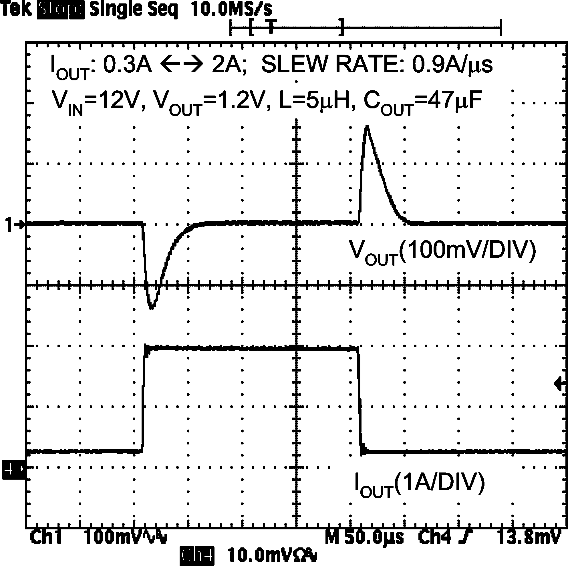 Figure 28. Load Step Response
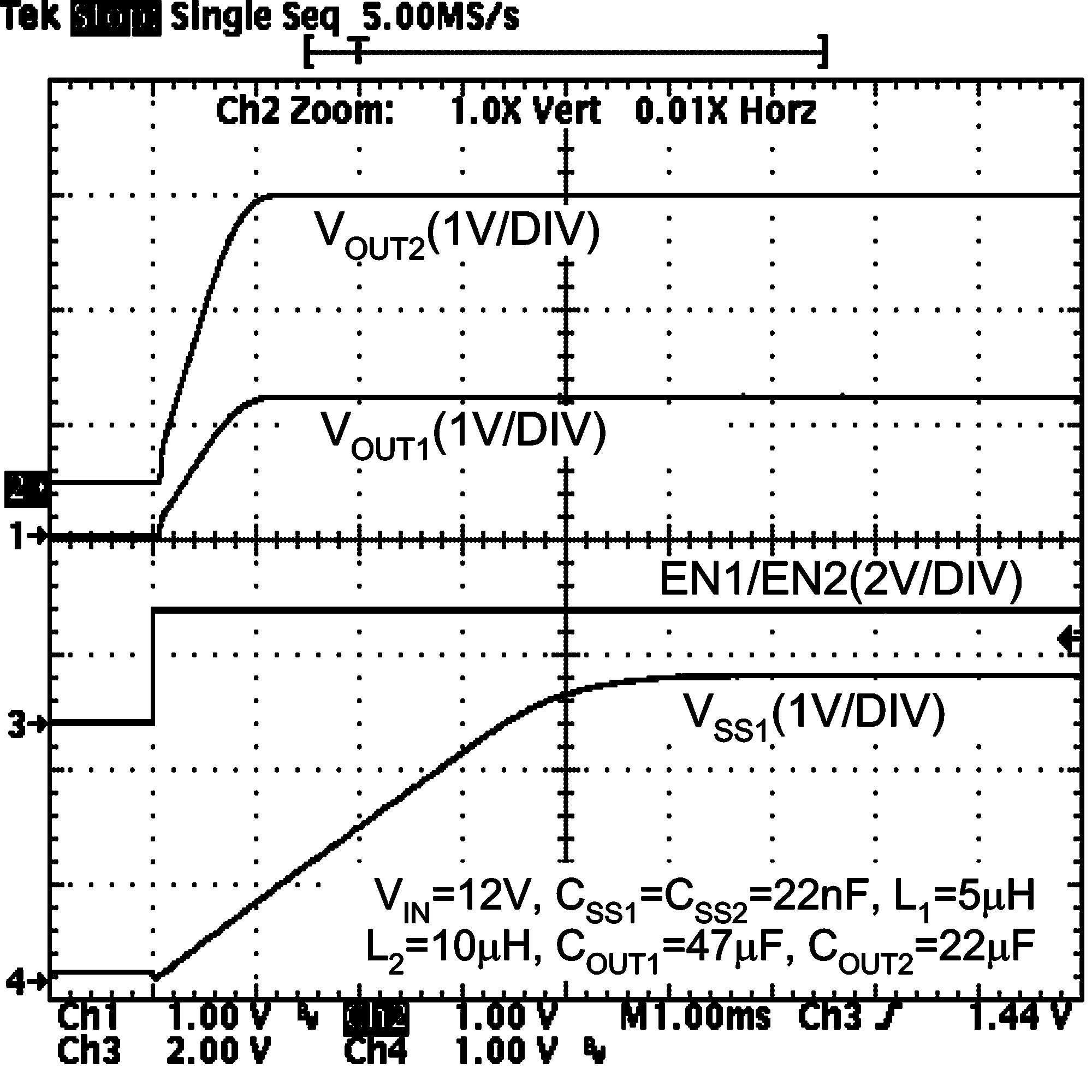 Figure 30. Start-Up (No Load)
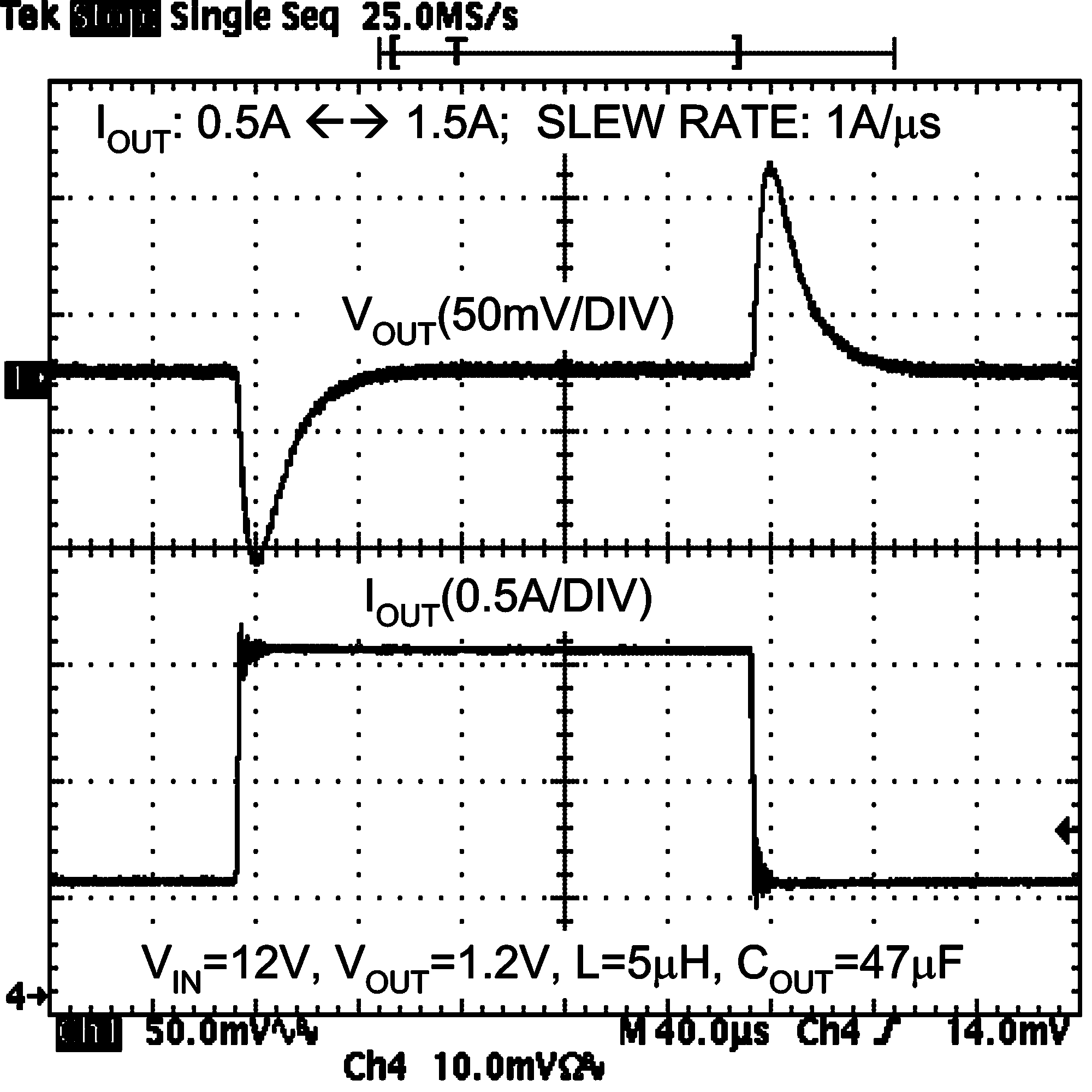 Figure 29. Load Step Response
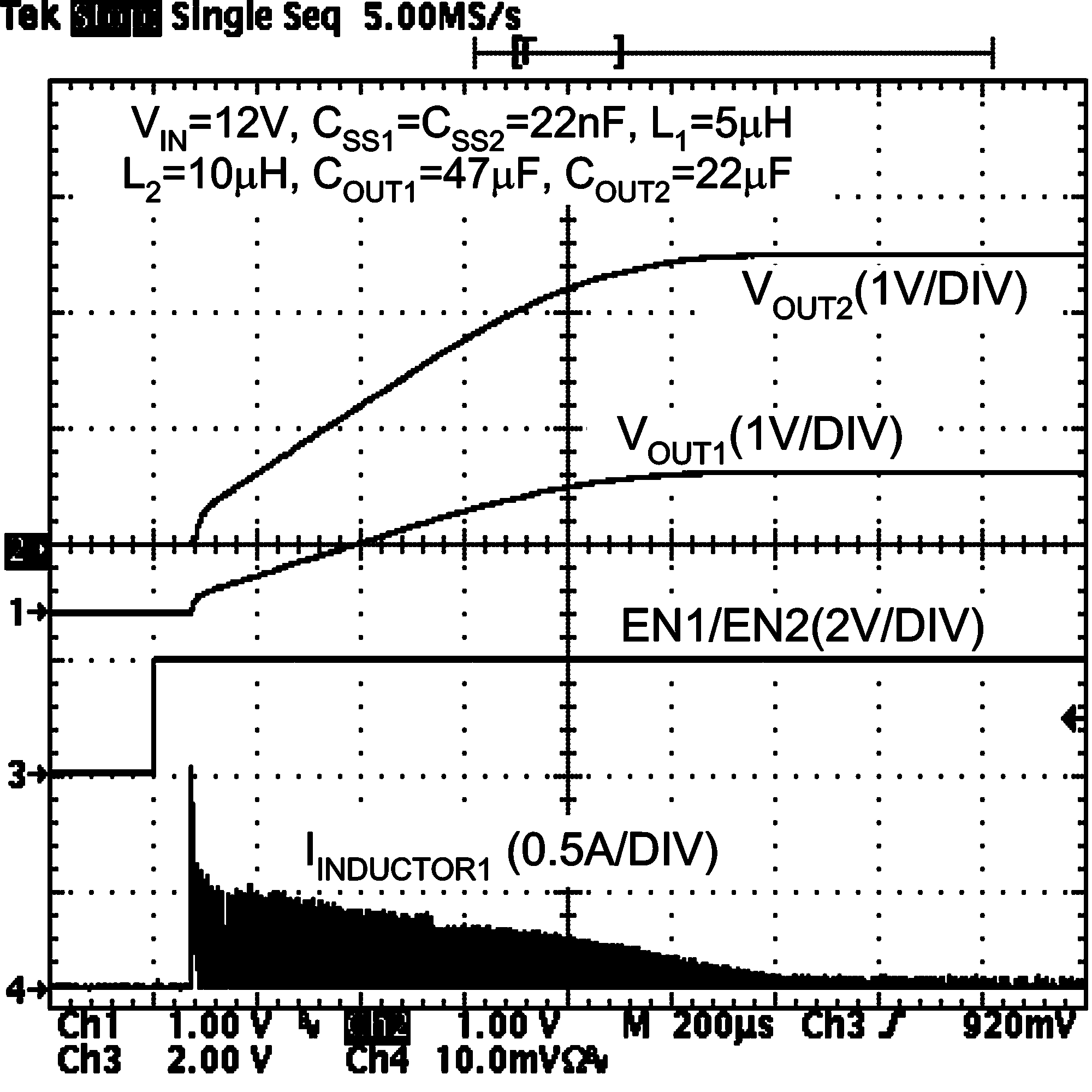 Figure 31. Start-Up (No Load)
8.2.2 LM26400Y Design Example 2
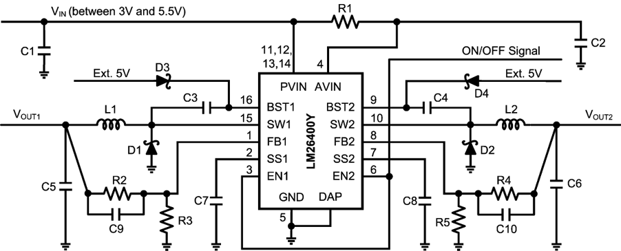
Table 3. Bill of Materials (Circuit 2, VIN = 3 V to 5 V, Output1 = 1.2 V/2 A, Output2 = 1.8 V/2 A)
| PART | DESCRIPTION | PART VALUES | PHYSICAL SIZE | PART NUMBER | MANUFACTURER |
|---|---|---|---|---|---|
| C1 | Capacitor, Ceramic | 10 µF, 6.3 V, X5R | 1206 | GRM319R60J106KE19 | Murata |
| C2 | Capacitor, Ceramic | 0.22 µF, 6.3 V, X5R | 0402 | JMK105BJ224KV-F | Taiyo Yuden |
| C3 | Capacitor, Ceramic | 0.1 µF, 6.3 V, X5R | 0402 | C1005X5R0J104K | TDK |
| C4 | Capacitor, Ceramic | 0.1 µF, 6.3 V, X5R | 0402 | C1005X5R0J104K | TDK |
| C5 | Capacitor, Ceramic | 100 µF, 6.3 V, X5R | 1210 | GRM32ER60J107ME20L | Murata |
| C6 | Capacitor, Ceramic | 100 µF, 6.3 V, X5R | 1210 | GRM32ER60J107ME20L | Murata |
| C7 | Capacitor, Ceramic | 0.012 µF, 6.3 V, X5R | 0402 | C0402C123K9PACTU | Kemet |
| C8 | Capacitor, Ceramic | 0.012 µF, 6.3 V, X5R | 0402 | C0402C123K9PACTU | Kemet |
| C9 | Capacitor, Ceramic | 0.027 µF, 6.3 V, X5R | 0402 | C0402C273K9PACTU | Kemet |
| C10 | Capacitor, Ceramic | 0.027 µF, 6.3 V, X5R | 0402 | C0402C273K9PACTU | Kemet |
| D1 | Diode, Schottky | 2 A, 30 V | SMB | MBRS230LT3G | ON Semiconductor |
| D2 | Diode, Schottky | 2 A, 30 V | SMB | MBRS230LT3G | ON Semiconductor |
| L1 | Inductor | 5 µH, 2.2 A | 7 × 7 × 2.8 mm3 | CDRH6D26NP-5R0NC | Sumida |
| L2 | Inductor | 5 µH, 2.2 A | 7 × 7 × 2.8 mm3 | CDRH6D26NP-5R0NC | Sumida |
| R1 | Resistor | 10 Ω, 1% | 0402 | CRCW040210R0FK | Vishay |
| R2 | Resistor | 5.9 kΩ, 1% | 0402 | CRCW04025K90FK | Vishay |
| R3 | Resistor | 5.9 kΩ, 1% | 0402 | CRCW04025K90FK | Vishay |
| R4 | Resistor | 11.8 kΩ, 1% | 0402 | CRCW040211K8FK | Vishay |
| R5 | Resistor | 5.90 kΩ, 1% | 0402 | CRCW04025K90FK | Vishay |
| U1 | Regulator | Dual 2-A Buck | HTSSOP-16 | LM26400YMH | Texas Instruments |