JAJSHM0A June   2019  – September 2019 OPA2834

PRODUCTION DATA.  

  1. 特長
  2. アプリケーション
  3. 概要
    1.     Device Images
      1.      1kHz FFT のプロット (VOUT = 1VRMS、RL = 100kΩ、G = 1)
      2.      ローサイドの電流シャント・モニタ
  4. 改訂履歴
  5. Device Comparison Table
  6. Pin Configuration and Functions
    1.     Pin Functions
  7. Specifications
    1. 7.1 Absolute Maximum Ratings
    2. 7.2 ESD Ratings
    3. 7.3 Recommended Operating Conditions
    4. 7.4 Thermal Information
    5. 7.5 Electrical Characteristics: 3V to 5V
    6. 7.6 Typical Characteristics: Vs = 5 V
    7. 7.7 Typical Characteristics: VS = 3.0 V
    8. 7.8 Typical Characteristics: ±2.5-V to ±1.5-V Split Supply
  8. Detailed Description
    1. 8.1 Overview
    2. 8.2 Functional Block Diagrams
    3. 8.3 Feature Description
      1. 8.3.1 Input Common-Mode Voltage Range
      2. 8.3.2 Output Voltage Range
      3. 8.3.3 Low-Power Applications and the Effects of Resistor Values on Bandwidth
      4. 8.3.4 Driving Capacitive Loads
    4. 8.4 Device Functional Modes
      1. 8.4.1 Split-Supply Operation (±1.35 V to ±2.7 V)
      2. 8.4.2 Single-Supply Operation (2.7 V to 5.4 V)
  9. Application and Implementation
    1. 9.1 Application Information
      1. 9.1.1 Noninverting Amplifier
      2. 9.1.2 Inverting Amplifier
    2. 9.2 Typical Applications
      1. 9.2.1 Low-Side Current Sensing
        1. 9.2.1.1 Design Requirements
        2. 9.2.1.2 Detailed Design Procedure
      2. 9.2.2 Field Transmitter Sensor Interface
      3. 9.2.3 Ultrasonic Flow Meters
      4. 9.2.4 Microphone Pre-Amplifier
  10. 10Power Supply Recommendations
  11. 11Layout
    1. 11.1 Layout Guidelines
    2. 11.2 Layout Examples
  12. 12デバイスおよびドキュメントのサポート
    1. 12.1 ドキュメントのサポート
      1. 12.1.1 関連資料
    2. 12.2 ドキュメントの更新通知を受け取る方法
    3. 12.3 コミュニティ・リソース
    4. 12.4 商標
    5. 12.5 静電気放電に関する注意事項
    6. 12.6 Glossary
  13. 13メカニカル、パッケージ、および注文情報

パッケージ・オプション

メカニカル・データ(パッケージ|ピン)
サーマルパッド・メカニカル・データ
発注情報

Typical Characteristics: VS = 3.0 V

VS+ = 3 V, VS– = 0 V, RF = 0 Ω, RL = 5 kΩ, CL = 4 pF, input and output referenced to mid-supply, and TA ≈ 25°C (unless otherwise noted)
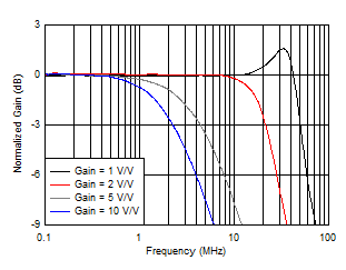
OPA2834 D114_3V_NonInv_SSBW.gif
VO = 20 mVPP
Figure 15. Noninverting Small-Signal Frequency Response
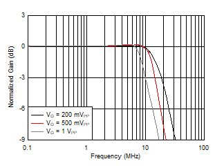
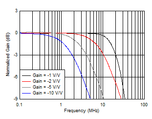
OPA2834 D116_3V_NonInv_LSBW.gif
Gain = 2 V/V
Figure 17. Noninverting Large-Signal Bandwidth
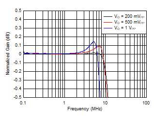
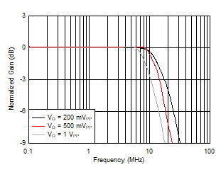
OPA2834 D207_NEW_3V_noninverting_flatness.gif
Gain = 2 V/V
Figure 19. Noninverting Large-Signal Frequency Response Flatness
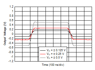
OPA2834 D308_3V_NonInv_Stepresonse.gif
Gain = 2 V/V
Figure 21. Noninverting Step Response
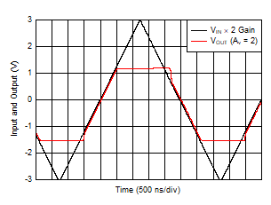
OPA2834 D311_3V_Noninv_Overdrive.gif
Gain = 2 V/V
Figure 23. Noninverting Overdrive Recovery
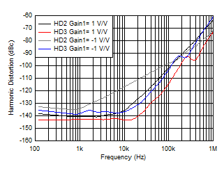
OPA2834 D122_3V_HD_Vs_Frequency.gif
VO = 1 VPP
Figure 25. Harmonic Distortion vs Frequency
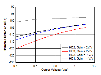
OPA2834 D123_3V_HD_vs_Vout.gif
f = 100 kHz
Figure 27. Harmonic Distortion vs Output Voltage
OPA2834 D115_3V_Inv_SSBW.gif
VO = 20 mVPP
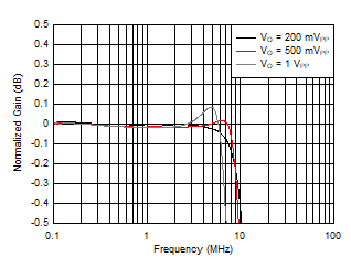
Figure 16. Inverting Small-Signal Frequency Response
OPA2834 D117_3V_Inv_LSBW.gif
Gain = –1 V/V
Figure 18. Inverting Large-Signal Bandwidth
OPA2834 D208_NEW_3V_inverting_flatnesslsbw.gif
Gain = –1 V/V
Figure 20. Inverting Large-Signal Frequency Response Flatness
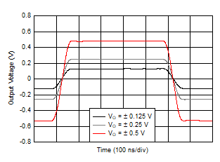
OPA2834 D309_New_3V_Inverting_step_response.gif
Gain = –1 V/V
Figure 22. Inverting Step Response
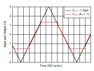
OPA2834 D310_Inverting_3V_OverdriveRecovery.gif
Gain = –1 V/V
Figure 24. Inverting Overdrive Recovery
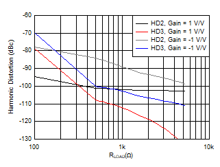
OPA2834 D312_3V_HD_Vs_Rload.gif
VO = 1 VPP, f = 100 kHz
Figure 26. Harmonic Distortion vs RLOAD
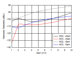
OPA2834 D204_New_3V_HD_Vs_Gain.gif
f = 100 kHz, VO = 1 VPP
Figure 28. Harmonic Distortion vs Gain Magnitude