JAJSIA9A December 2019 – May 2022 TUSS4440
PRODUCTION DATA
- 1 特長
- 2 アプリケーション
- 3 概要
- 4 Revision History
- 5 Pin Configuration and Functions
-
6 Specifications
- 6.1 Absolute Maximum Ratings
- 6.2 ESD Ratings
- 6.3 Recommended Operating Conditions
- 6.4 Thermal Information
- 6.5 Power-Up Characteristics
- 6.6 Transducer Drive
- 6.7 Receiver Characteristics
- 6.8 Echo Interrupt Comparator Characteristics
- 6.9 Digital I/O Characteristics
- 6.10 Switching Characteristics
- 6.11 Typical Characteristics
- 7 Detailed Description
- 8 Application and Implementation
- 9 Power Supply Recommendations
- 10Layout
- 11Device and Documentation Support
- 12Mechanical, Packaging, and Orderable Information
パッケージ・オプション
メカニカル・データ(パッケージ|ピン)
- RTJ|20
サーマルパッド・メカニカル・データ
- RTJ|20
発注情報
8.2 Typical Application
 Figure 8-1 TUSS4440 Application Diagram
Table 8-1 Recommended Component Values for Typical Applications
| DESIGNATOR | VALUE | COMMENT |
|---|---|---|
| RPWR | 10 Ω | Optional (to limit fast voltage transient on VPWR pin during power up) |
| R(INP) | 3kΩ (1/4 Watt) | Optional for EMI/ESD robustness |
| CPWR1 | 50V, 100nF | |
| CPWR2 | 40V, 100µF | |
| CVDD | >5V, 10nF | |
| CINP | 40V, 330pF | |
| CINN | >5V, CINN | Use equation below to estimate value of CINN depending on the burst frequency
Equation 2. 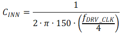 |
| CFLT | 5V, CFLT | Use equation below to estimate value of CFLT depending on the burst frequency . Value has to be optimized for application depending on noise and response time requirements.
Equation 3. 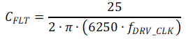 |
| CT | Optional. Value depends on transducer and transformer used | |
| RT | Optional. Value depends on transducer and transformer used | |
| D1 | 1N4001 or equivalent | Optional for reverse supply and reverse current protection. |
| XDCR (transducer) | Example devices for low-frequency range: Closed top: 40 kHz: PUI Audio UTR-1440K-TT-R Open top: muRata MA40H1S-R, SensComp 40LPT16, Kobitone 255-400PT160-ROX Example devices for high-frequency range: Closed top: 300 kHz: Murata MA300D1-1 | |
| XFMR (transformer) | Example devices: TDK EPCOS B78416A2232A003, muRata-Toko N1342DEA-0008BQE=P3, Mitsumi K5-R4 |