DLPU106A March   2021  – October 2021 DLP3021-Q1


  1.   Abstract
  2. 1Trademarks
  3. 2DLP3021-Q1 Electronics EVM Overview
    1. 2.1 Introduction
    2. 2.2 What is in the DLP3021-Q1 Light Engine EVM
      1. 2.2.1 Formatter Subsystem
      2. 2.2.2 Illumination Subsystem
      3. 2.2.3 Light Engine
      4. 2.2.4 Cables
    3. 2.3 Non-Optical Specifications
      1. 2.3.1 Electrical Specifications
      2. 2.3.2 Component Temperature Ratings
      3. 2.3.3 LED Driver Design
      4. 2.3.4 Video Specification
  4. 3Quick Start
    1. 3.1 Kit Assembly Instructions
    2. 3.2 Software Installation
    3. 3.3 Power-Up
    4. 3.4 Select Display Content
    5. 3.5 LED Driver
  5. 4Optics and Mechanics
  6. 5Software
    1. 5.1 DLP Composer
      1. 5.1.1 Default Register Configuration
      2. 5.1.2 Illumination
      3. 5.1.3 Sequence Set
      4. 5.1.4 Degamma Curves
      5. 5.1.5 Image/Video
      6. 5.1.6 Flash Blocks
      7. 5.1.7 Flash Programming
    2. 5.2 DLP Control Program
      1. 5.2.1 Connection
      2. 5.2.2 Scripting
      3. 5.2.3 Registers
      4. 5.2.4 Commands
    3. 5.3 MSP430 Example Code
  7. 6Revision History

MSP430 Example Code

When power is applied to the system, the FPGA configuration is loaded to the FPGA. Depending on the default configuration, the FPGA begins loading bit-planes to the DMD and sequencing the LED enables for each bit plane loaded. Alternatively, a microcontroller such as the MSP430G2553-Q1 on the EVM, can issue commands to the FPGA via SPI to enable video playback, change videos, read DMD temperature via the TMP411, or adjust current levels to the LEDs. The MSP430 Example Code (DLPC138) is a Code Composer Studio example project available for users to edit and refer to for a custom Local Host Control operation mode implementation.
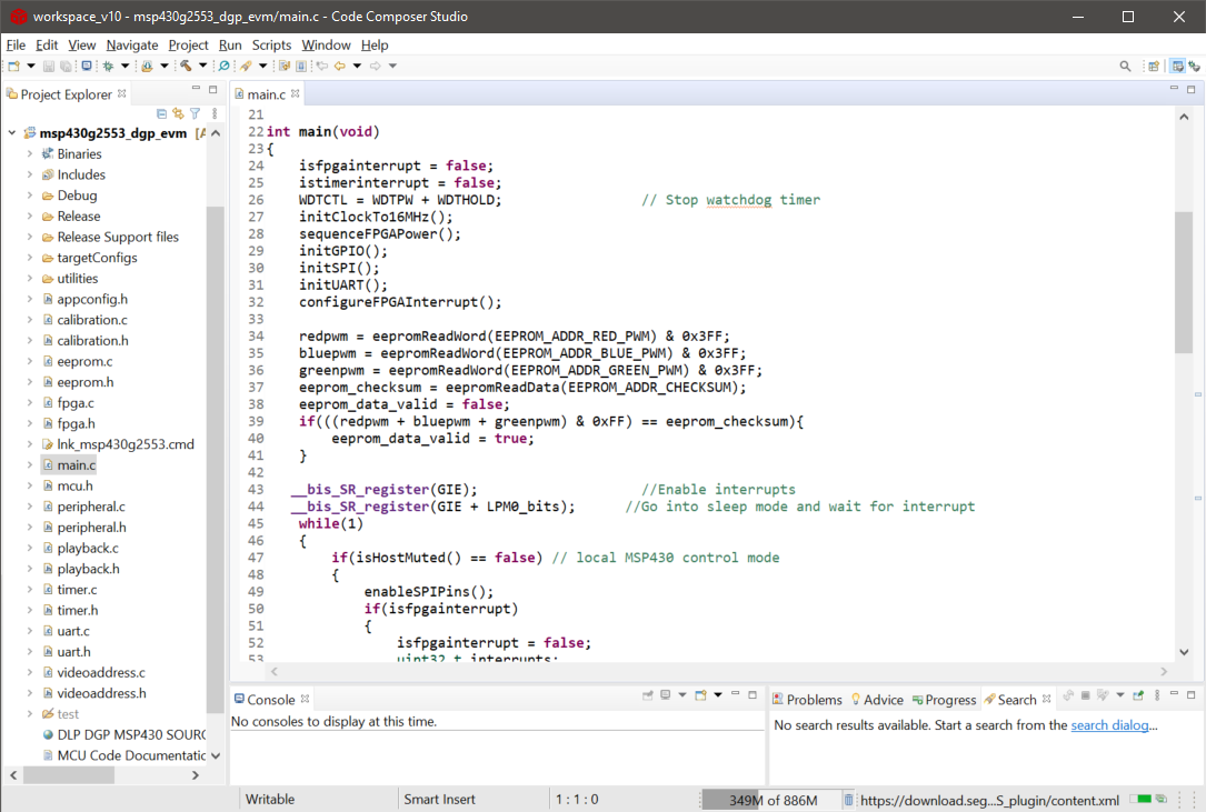
GUID-20210126-CA0I-M3WD-VGLN-FZVBJCQBBPDB-low.pngFigure 5-15 MSP430G2553-Q1 Code Composer Example Project for DGP EVM