JAJSDQ6C June   2012  – September 2017

PRODUCTION DATA.  

  1. 特長
  2. アプリケーション
  3. 概要
  4. 改訂履歴
  5. Pin Configuration and Functions
  6. Specifications
    1. 6.1  Absolute Maximum Ratings
    2. 6.2  ESD Ratings
    3. 6.3  Recommended Operating Conditions
    4. 6.4  Thermal Information
    5. 6.5  Electrical Characteristics: Front-End Amplification (Weight-Scale Signal Chain)
    6. 6.6  Electrical Characteristics: Body Composition Measurement Front-End
    7. 6.7  Electrical Characteristics: Analog-to-Digital Converter
    8. 6.8  Electrical Characteristics: Digital Input/Output
    9. 6.9  Timing Requirements: Serial Interface Timing
    10. 6.10 Typical Characteristics
  7. Detailed Description
    1. 7.1 Overview
    2. 7.2 Functional Block Diagram
    3. 7.3 Feature Description
      1. 7.3.1 Weight-Scale Analog Front-End
        1. 7.3.1.1 Input Common Mode Range
        2. 7.3.1.2 Input Differential Dynamic Range
        3. 7.3.1.3 Offset Correction DAC
          1. 7.3.1.3.1 Offset Correction Example
      2. 7.3.2 Body Composition Measurement Analog Front-End
        1. 7.3.2.1 AC Rectification
        2. 7.3.2.2 I/Q Demodulation
      3. 7.3.3 Digitizer
        1. 7.3.3.1 Multiplexer
        2. 7.3.3.2 Analog-to-Digital Converter
      4. 7.3.4 Reset and Power-Up
      5. 7.3.5 Duty Cycling for Low Power
    4. 7.4 Device Functional Modes
      1. 7.4.1 Operating Modes
    5. 7.5 Programming
      1. 7.5.1 Serial Interface
        1. 7.5.1.1 SPI Enable (STE)
        2. 7.5.1.2 Serial Clock (SCLK)
        3. 7.5.1.3 Data Input (SDIN)
        4. 7.5.1.4 Data Output (SDOUT)
        5. 7.5.1.5 Data Ready (RDY)
    6. 7.6 Register Maps
      1. 7.6.1 Register Map
        1. 7.6.1.1  ADC_DATA_RESULT (Address 0x00, Default 0x0000)
        2. 7.6.1.2  ADC_CONTROL_REGISTER1 (Address 0x01, Default 0x01C3)
        3. 7.6.1.3  MISC_REGISTER1 (Address 0x02, Default 0x8000)
        4. 7.6.1.4  MISC_REGISTER2 (Address 0x03, Default 0x7FFF)
        5. 7.6.1.5  DEVICE_CONTROL1 (Address 0x09, Default 0x0000)
        6. 7.6.1.6  ISW_MUX (Address 0x0A, Default 0x0000)
        7. 7.6.1.7  VSENSE_MUX (Address 0x0B, Default 0x0000)
        8. 7.6.1.8  IQ_MODE_ENABLE (Address 0x0C, Default 0x0000)
        9. 7.6.1.9  WEIGHT_SCALE_CONTROL (Address 0x0D, Default 0x0000)
        10. 7.6.1.10 BCM_DAC_FREQ (Address 0x0E, Default 0x0000)
        11. 7.6.1.11 DEVICE_CONTROL2 (Address 0x0F, Default 0x0000)
        12. 7.6.1.12 ADC_CONTROL_REGISTER2 (Address 0x10, Default 0x0000)
        13. 7.6.1.13 MISC_REGISTER3 (Address 0x1A, Default 0x0000)
  8. Application and Implementation
    1. 8.1 Application Information
      1. 8.1.1 BCM Channel Connections
      2. 8.1.2 Handling Oscillation of the Excitation Amplifier
      3. 8.1.3 Achieving Deterministic Phase in the IQ Mode
    2. 8.2 Typical Application
      1. 8.2.1 Design Requirements
      2. 8.2.2 Detailed Design Procedure
      3. 8.2.3 Application Curve
  9. Power Supply Recommendations
    1. 9.1 Power-Supply Recommendation and Initialization
  10. 10Layout
    1. 10.1 Layout Guidelines
    2. 10.2 Layout Example
  11. 11デバイスおよびドキュメントのサポート
    1. 11.1 ドキュメントの更新通知を受け取る方法
    2. 11.2 コミュニティ・リソース
    3. 11.3 商標
    4. 11.4 静電気放電に関する注意事項
    5. 11.5 Glossary
  12. 12メカニカル、パッケージ、および注文情報

Pin Configuration and Functions

PN Package
80-Pin LQFP
Top View
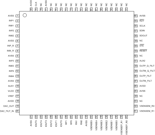
AFE4300 Pinout_SBAS586.gif

Pin Functions

PIN I/O DESCRIPTION
NAME NUMBER
AAUX1 15 I Auxiliary input to the ADC
AAUX2 51 I Auxiliary input to the ADC
AVDD 18, 46, 80 Supply (3.3 V)
AVSS 1, 6, 9, 14, 21, 32, 45, 60, 77 Ground
CLK 79 I 1-MHz clock
DAC_FILT_IN 20 I Current generator input. Connect ac blocking capacitor between this pin and pin 19.
DACOUT 19 O DAC output. Connect ac blocking capacitor between this pin and pin 20.
INM1 3 I Instrumentation amplifier differential inputs for each of the four weight-scale channels
INM2 5
INM3 11
INM4 13
INP1 2
INP2 4
INP3 10
INP4 12
INM_R 8 Connection of gain setting resistor for the instrumentation amplifier
INP_R 7
IOUT0 27 O Current source output to electrodes
IOUT1 26
IOUT2 25
IOUT3 24
IOUT4 23
IOUT5 22
NC 43, 44, 52, 55, 61-76, 78 Do not connect
OUTM_I_FILT 47 I channel demodulator low pass filter, connect 10 µF between both pins
OUTP_I_FILT 48
OUTM_Q_FILT 49 Q channel demodulator low pass filter, connect 10 µF between both pins
OUTP_Q_FILT 50
RDY 59 O Data ready
RN0 31 O Current source output to calibration resistors
RN1 30
RP0 29
RP1 28
RST 53 I Reset. 0: reset, 1: normal operation.
SCLK 58 I Serial clock to latch input data (negative edge latch)
SDIN 57 I Serial data input
SDOUT 56 O Serial data output
STE 54 I SPI enable. 0: shift data in, 1: disable.
VLDO 16 O LDO output to supply the bridges (~1.7 V), connect 470 nF to AVSS
VREF 17 O Reference voltage (connect 470 nF to AVSS)
VSENSEM_R0 42 I Input to differential amplifier from calibration resistors
VSENSEM_R1 41
VSENSEP_R0 40
VSENSEP_R1 39
VSENSE0 38 I Input to differential amplifier from electrode
VSENSE1 37
VSENSE2 36
VSENSE3 35
VSENSE4 34
VSENSE5 33