JAJU617A October 2018 – May 2022
- 概要
- Resources
- 特長
- アプリケーション
- 5
- 1System Description
- 2System Overview
- 3Hardware, Software, Testing Requirements, and Test Results
- 4Design Files
- 5Software Files
- 6Related Documentation
- 7Terminology
- 8Revision History
3.2.2 Test Results
Power consumption is primarily determined by luminous output. Maximum brightness of 90 lumens requires about 7.1 W of power, but this is only needed on extremely sunny days. Nominal HUD brightness will be closer to 25 lumens, which only requires about 2.9 W of power.
| HUD Brightness | Calculated Luminous Output | Measured System Power (W) |
|---|---|---|
| Max Brightness | 90 lumens | 7.1 |
| Medium Brightness | 75 lumens | 5.9 |
| Low Brightness | 25 lumens | 2.9 |
| Min Brightness | 0.018 lumens | 1.8 |
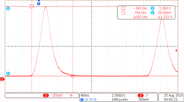
To support the lowest brightness ranges, around 1/5000th of max brightness, the LED driver must create very small, short pulses of light. The LED driver included in this design supports LED pulses below 1 µs. Figure 3-1 below shows a short pulse on the output of the photodiode signal, measured at TP6.
For more information on the LED driver and dimming functionality, please see the Enabling the Next Generation of Automotive Head-Up Display Systems application note.
 Figure 3-1 Shortest LED Pulse of 952 ns