JAJU837 March   2022


  1.   概要
  2.   Resources
  3.   特長
  4.   アプリケーション
  5.   5
  6. 1System Description
  7. 2System Overview
    1. 2.1 Block Diagram
    2. 2.2 Highlighted Products
      1. 2.2.1 TMAG5170
      2. 2.2.2 DRV5055A4
    3. 2.3 Design Considerations
      1. 2.3.1 Magnet Selection
      2. 2.3.2 Magnet Shape
      3. 2.3.3 Magnet Rotation Speed
      4. 2.3.4 Sensor Location
      5. 2.3.5 Expected Performance
      6. 2.3.6 Layout for Sensor Location
      7. 2.3.7 45° Alignment
  8. 3Hardware, Software, Testing Requirements, and Test Results
    1. 3.1 Hardware Requirements
    2. 3.2 Test Setup
      1. 3.2.1 Test Equipment
      2. 3.2.2 Test Hardware Configuration
      3. 3.2.3 Test Software Configuration and Initial Data Capture
    3. 3.3 Test Results
      1. 3.3.1 Calibration Methods
      2. 3.3.2 TMAG5170 On-Axis
      3. 3.3.3 TMAG5170 In-Plane
      4. 3.3.4 TMAG5170 Off-Axis
      5. 3.3.5 TMAG5170 45° Alignment
      6. 3.3.6 DRV5055 Off Axis Result
  9. 4Design and Documentation Support
    1. 4.1 Design Files
      1. 4.1.1 Schematics
      2. 4.1.2 BOM
    2. 4.2 Tools and Software
    3. 4.3 Documentation Support
    4. 4.4 サポート・リソース
    5. 4.5 Trademarks

TMAG5170 Off-Axis

A third option represents every other possible location about the magnet. While the expected inputs for on-axis and in-plane were purely two dimensional, it is normal for the off-axis case to have field components in all three directions.

With the versatility of TMAG5170 to detect 3D fields, it is possible to use various sensor orientations and use any two vector components which are 90° out of phase. In this case XZ field components were used to calculate angular position.

The observed error for this alignment were similar to what was observed with the In-Plane Configuration.
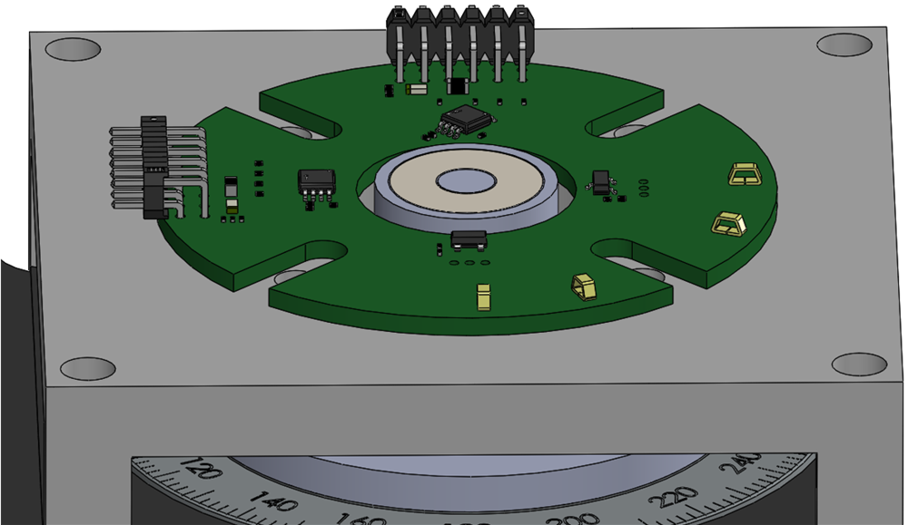
GUID-20220208-SS0I-C1XM-41GM-SCMQ4JRWDZ4M-low.png Figure 3-16 Off-Axis Configuration

Off-Axis Mechanical Angle Error shows the resulting error for both a direct arctangent calculation and for the CORDIC output after applying the harmonic data.

Figure 3-17 Off-Axis Mechanical Angle Error
Table 3-4 Off-Axis Harmonic Correction Factors
HARMONIC αi βi
1 –6.97 –0.55
2 –0.05 1.12
3 –0.15 0.07
4 –0.13 –0.13
5 0.02 0.03

Off-Axis Calibrated Angle Error shows the resulting error after applying the harmonic data.

Figure 3-18 Off-Axis Calibrated Angle Error