JAJU873 August 2020
- 概要
- リソース
- 特長
- アプリケーション
- 5
- 1 System Description
- 2System Overview
- 3Hardware, Software, Testing Requirements, and Test Results
- 4Design and Documentation Support
- 5About the Author
3.3.1 Motor Test Result
The following motor tests were conducted:
- Motor Identification
- Wonsmart WS7040_24_V200
- Boreasa C65MS1_L5
- No-Load Step Response
- Current Step Response
- Speed Step Response (10kRPM to 40kRPM and 40kRPM to 10kRPM)
Tests were done at room temperature around 22°C to 23°C, with a PWM of 45 kHz. The current and speed controllers were set to 45 kHz and 3 kHz. The user control parameters are configured in the user.h file.
#define USER_PWM_FREQ_kHz                (45.0)
#define USER_NUM_CTRL_TICKS_PER_CURRENT_TICK   (1)
#define USER_NUM_CTRL_TICKS_PER_SPEED_TICK  (15)
Motor Identification
When identifying the motor parameters, the proj_lab02c from MotorWare was used. The following parameters were identified for the Wonsmart_WS7040_24_V200 motor:
#define USER_MOTOR_TYPE                 MOTOR_Type_Pm
#define USER_MOTOR_NUM_POLE_PAIRS       (1)
#define USER_MOTOR_Rs                   (0.653760076)
#define USER_MOTOR_Ls_d                 (0.000252834143)
#define USER_MOTOR_Ls_q                 (0.000252834143)
#define USER_MOTOR_RATED_FLUX           (0.0168186165)
The following parameters were identified for the Boreasa_C65MS1_L5 motor:
#define USER_MOTOR_TYPE MOTOR_Type_Pm
#define USER_MOTOR_NUM_POLE_PAIRS (1)
#define USER_MOTOR_Rs (0.348989993)
#define USER_MOTOR_Ls_d (0.000173127264)
#define USER_MOTOR_Ls_q (0.000173127264)
#define USER_MOTOR_RATED_FLUX (0.0160903856)
Once the motor parameters are determined from lab02c and saved to user.h, the user can proceed to lab05h for step response testing.
No-Load Step Response
When measuring the step reponse, proj_lab05h was used. The motors tested were Wonsmart_WS7040_24_V200 and Boreasa_C65MS1_L5.
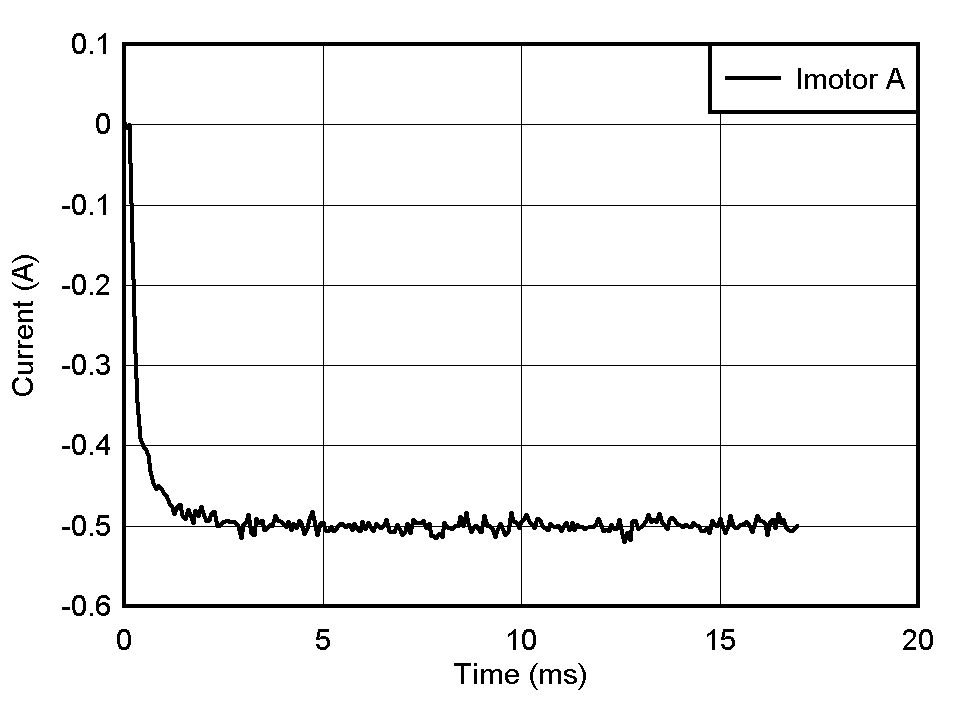
Figure 3-15 shows the Wonsmart Id current controller PI step response.
 Figure 3-15 Wonsmart Id Current Controller PI
Step Response
Figure 3-15 Wonsmart Id Current Controller PI
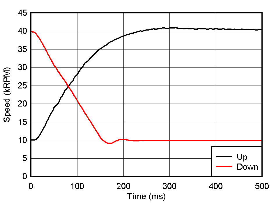
Step ResponseFigure 3-16 shows the Wonsmart speed controller PI step response.
 Figure 3-16 Wonsmart Speed Controller PI Step
Response
Figure 3-16 Wonsmart Speed Controller PI Step
Response| CONTROLLER | KP | KI |
|---|---|---|
| Current controller at 45 kHz | 0.395 | 0.172 |
| Speed controller at 3 kHz |
12 |
0.08 |
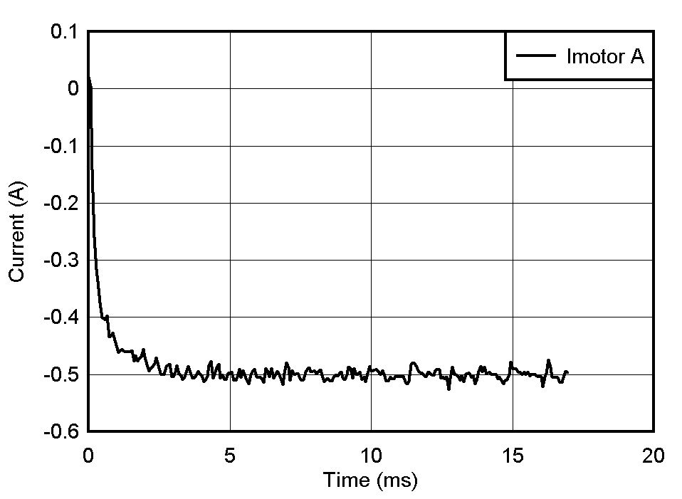
Figure 3-17 shows the Boreasa Id current controller PI step response.
 Figure 3-17 Boreasa Id Current Controller PI
Step Response
Figure 3-17 Boreasa Id Current Controller PI
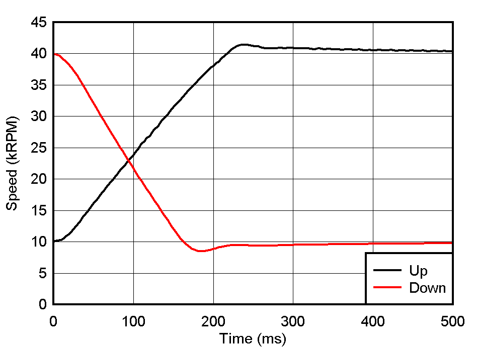
Step ResponseFigure 3-18 shows the Boreasa speed controller PI step response.
 Figure 3-18 Boreasa Speed Controller PI Step
Response
Figure 3-18 Boreasa Speed Controller PI Step
Response| CONTROLLER | KP | KI |
|---|---|---|
| Current controller at 45 kHz | 0.27 | 0.134 |
| Speed controller at 3 kHz | 30 | 0.12 |
These PI values are optimized for this specific speed range. In reality, the designer may have multiple sets of PI values depending on the specific operation (for example, one set low speed and another set for high speed).