JAJU880 December   2022


  1.   概要
  2.   リソース
  3.   特長
  4.   アプリケーション
  5.   5
  6. 1System Description
  7. 2System Overview
    1. 2.1 Block Diagram
    2. 2.2 Design Considerations
      1. 2.2.1 Auxiliary Power Strategy
      2. 2.2.2 High-Side N-Channel MOSFET
      3. 2.2.3 Stacked AFE Communication
    3. 2.3 Highlighted Products
      1. 2.3.1 BQ76942
      2. 2.3.2 LM5168
      3. 2.3.3 ISO1640
      4. 2.3.4 TCAN1042HV
      5. 2.3.5 THVD2410
      6. 2.3.6 TPS7A25
      7. 2.3.7 MSP430FR2155
      8. 2.3.8 TMP61
      9. 2.3.9 TPD2E007
  8. 3Hardware, Software, Testing Requirements, and Test Results
    1. 3.1 Hardware Requirements
    2. 3.2 Test Setup
    3. 3.3 Test Results
      1. 3.3.1 Cell Voltage Accuracy
      2. 3.3.2 Pack Current Accuracy
      3. 3.3.3 Auxiliary Power and System Current Consumption
      4. 3.3.4 Protection
      5. 3.3.5 Working Modes Transition
      6. 3.3.6 ESD Performance
  9. 4Design and Documentation Support
    1. 4.1 Design Files
      1. 4.1.1 Schematics
      2. 4.1.2 BOM
    2. 4.2 Tools and Software
    3. 4.3 Documentation Support
    4. 4.4 サポート・リソース
    5. 4.5 Trademarks
  10. 5About the Author

Working Modes Transition

This design has three working modes: normal mode, standby mode, and ship mode. When the pack is charging or discharging, the pack is in normal mode. Sleep mode is when there is no charging nor discharging, the pack is waiting for a charger or load attachment. Shutdown mode is a very low current consumption mode which saves energy and helps to avoid battery over discharge when the pack or cell voltage is low. Figure 3-17 shows different working mode transitions.
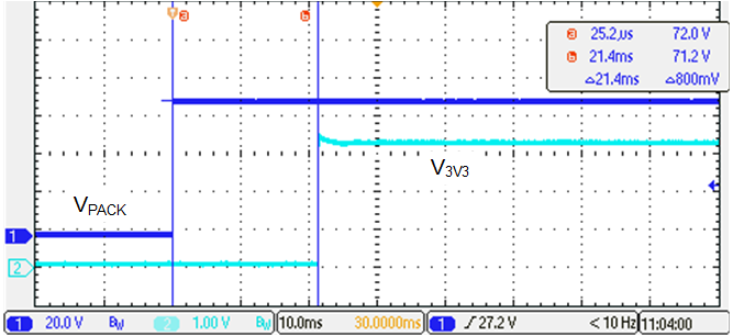
GUID-20221115-SS0I-2DRB-SRCJ-WLVC24MNDJST-low.png Figure 3-17 Ship Mode to Normal Mode

When TIDA-010247 is in ship mode and both BQ76942 devices are in shutdown mode. The bottom BQ76942 detects charger attached on PACK side and wakes up to normal mode, enabling REG1 or REG2 to power on the MCU.