SBAA487 January 2021 ADS8664 , ADS8668 , ADS8674 , ADS8678 , ADS8684 , ADS8684A , ADS8686S , ADS8688 , ADS8688A , ADS8694 , ADS8698
3.1 Averaging with Sequencer
The ADS8686S has a highly configurable channel sequencer to reduce the overhead of switching channels on the backend controller or processor, refer to section 7.4.2.5 Sequencer for details in ADS8686S data sheet. By configuring ADS8686S in a certain sequential order to scan the channels, the sample averaging per channel can be achieved to minimize the phase delay as much as possible. The Sequencer mode on the ADS8686S can be used to flexibly configure the sequence of channel switching to perform this operation.
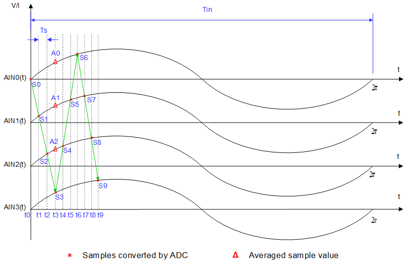
As a 4-channel example shown in Figure 3-1, the sequencer for sample averaging is configured as: AIN0 -> AIN1-> AIN2 - > AIN3 -> AIN2 -> AIN1 -> AIN0. The conversion data displayed at S0,S1…S6 are captured and converted at a t0, t1…t6 for each channel, the time interval between them is determined by the sampling rate of ADC (fs=1/Ts), the time interval between two samples is constant when the sampling rate of ADC is not changed.
 Figure 3-1 Averaged samples aligned with the
sample on AIN3
Figure 3-1 Averaged samples aligned with the
sample on AIN3The sample averaging is implemented by averaging the samples on each channel, for example, the averaged data SA0 on channel AIN0 is got by averaging the captured data S0 and S6, A0 = (S0+S6)/2, the same calculation can be used for the rest of channels, AIN1 and AIN2, so A1 = (S1+S5)/2 and A2 = (S2+S4)/2. Because the sampling interval is exactly same, so these averaged data (A0,A1 and A2) and the original sampled data(S3) are located at the same time position t3, all averaged values are highly close to the sample value S3 on the AIN3 channel if the same sinusoidal signal signal is applied on all input channels of the ADC. Hence, the phase delay between channels due to channel switching on the internal multiplexer is reduced and minimized with sample averaging.