SBAU230C August 2014 – March 2021
2 ADS8688EVM-PDK Overview
Table 1-1 lists the related documents that are available for download from Texas Instruments at
ADS8688EVM Features
- Hardware and software required for diagnostic testing as well as accurate performance evaluation of the ADS8688 ADC
- USB powered—no external power supply is required
- The PHI controller that provides a convenient communication interface to the ADS8688 ADC over USB 2.0 (or higher) for power delivery as well as digital input and output
- Easy-to-use evaluation software for 64-bit Microsoft Windows™7, Windows 8, and Windows 10 operating systems
- The software suite includes graphical tools for data capture, histogram analysis, and spectral analysis. This suite also has a provision for exporting data to a text file for post-processing. Fig
- Integrated 4.096-V voltage reference.
- Bipolar (±10.24 V, ±5,12 V, ±2.56 V ) or unipolar (0 V to 10.24 V, 0 V to 5.12 V) input ranges for each channel.
- Onboard, second-order, Butterworth, low-pass filters for four channels.
- Onboard regulator for generating a ±15-V bipolar supply for second-order, Butterworth, low-pass filters.
- Capable of accepting a ±100-mV signal on the negative analog inputs (AIN_xGND).
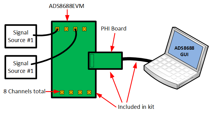
 Figure 2-1 System Connection for
Evaluation
Figure 2-1 System Connection for
EvaluationADS8688EVM Features:
- Eight input channels connected to external single ended signals source applied to SMA connectors or header
- Serial interface connects to the PHI controller via 60 pin connector (J3).
- Serial interface connects to the PHI controller via 60 pin connector (J2).
- All power for device from USB via PHI controller.
- Onboard ultra-low noise low-dropout (LDO) regulator generates 5.0V AVDD supply. Input to LDO from PHI controller.
- DVDD (3.3V) powered by PHI controller.