SBOA585 March 2024 ADS127L11 , ADS127L11 , ADS127L14 , ADS127L14 , ADS127L18 , ADS127L18 , ADS127L21 , ADS127L21 , PGA849 , PGA849 , PGA855 , PGA855
- 1
- Abstract
- Trademarks
- 1PGA855 and ADS127L21, 24-Bit, Delta-Sigma ADC Driver Circuit
- 2PGA855 Analog Front-End Filters
- 3ADS127Lx1 Delta-Sigma ADC and Digital Filter
- 4Approximate PGA855 Intrinsic Noise Analysis
- 5PGA855 and ADS127Lx1 System Noise
- 6PGA855 and ADS127Lx1 SNR and Noise Calculator
- 7PGA855 and ADS127Lx1 FFT Measured Performance
- 8Summary
- 9References
6 PGA855 and ADS127Lx1 SNR and Noise Calculator
The PGA855 and ADS127Lx1 SNR and Noise Calculator is a spreadsheet developed using Microsoft® Excel® that provides an estimate of the overall intrinsic noise performance of the acquisition system.
The tool calculates the noise contribution of the sensor resistance, PGA855, ADS127Lx1 ADC, REF6241 voltage reference and provides an estimate of the overall system noise bandwidth, SNR and effective resolution based on the data sheet noise specifications.
The delta-sigma ADC provides a trade-off between the output data rate and acquisition system bandwidth, against noise performance. The calculator facilitates selecting the ADC filter settings, and data rate or filter bandwidth, depending on the application required resolution, and sensor resistance.
The circuit designer enters the PGA855 circuit bandwidth, the RMS reference noise contribution at the ENBW, and selects the ADS127Lx1 digital filter settings and data rate. An optional field is available to enter the sensor equivalent resistance at each PGA855 input. Figure 7-13 shows the noise calculator inputs:
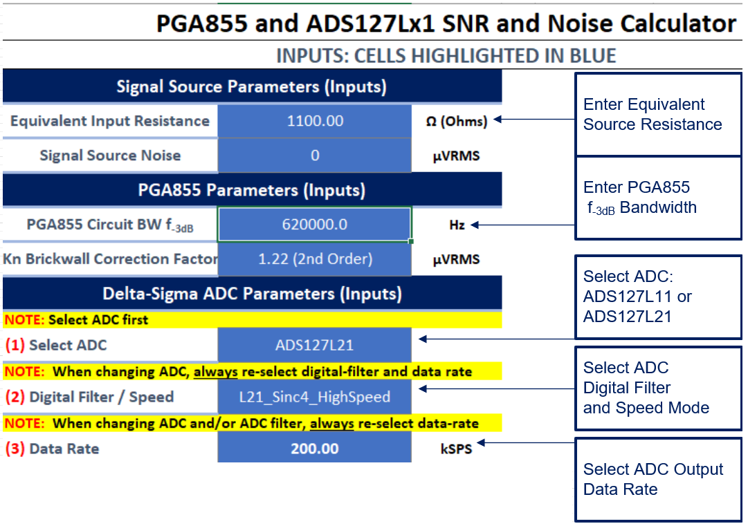 Figure 6-1 PGA855 and ADS127Lx1 Noise Calculator - Inputs
The calculator generates a plot of the system SNR and system effective resolution. Figure 7-7 shows the calculated SNR (dB) vs PGA gain in V/V, and Figure 7-8 shows the calculated system effective resolution in bits vs PGA gain in V/V.
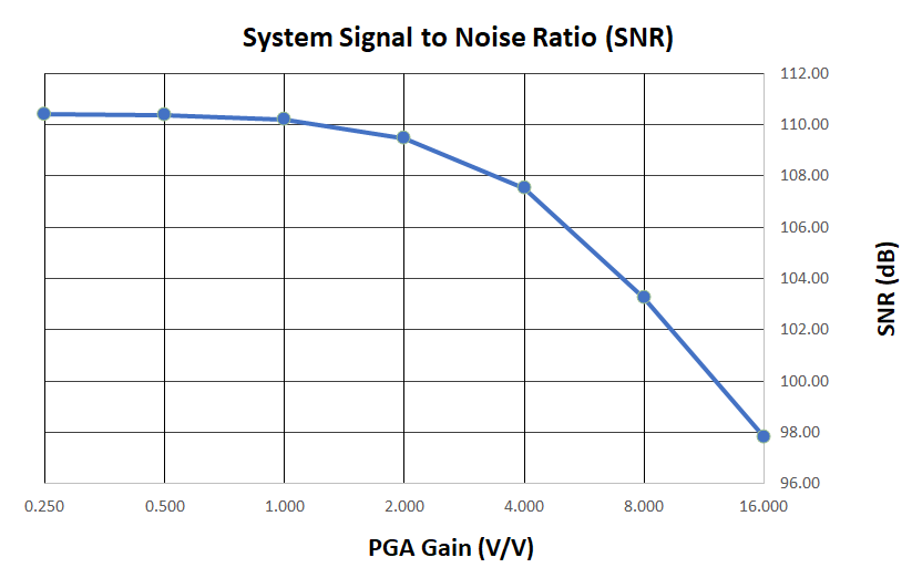
| High-Speed Mode, Sinc4, OSR = 64, Data Rate 200 kSPS |
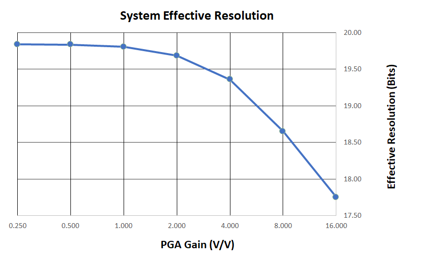
| High-Speed Mode, Sinc4, OSR = 64, Data Rate 200 kSPS |
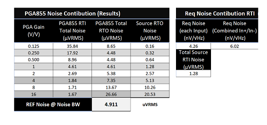
The PGA855 and ADS127Lx1 SNR and Noise Calculator also generates a table with an estimate of the equivalent intrinsic noise of the acquisition system in µVRMS, referred to the input of the PGA855 (RTI) or to the output of the PGA855 (RTO). In addition, it provides a separate table showing the noise contribution of the PGA855 circuit stand-alone, and the source or sensor noise contribution. Figure 6-4 and Figure 6-5 show a table with results as displayed in the tool, when selecting Sinc4 filter at 200-kSPS with REQ = 1.1kΩ.
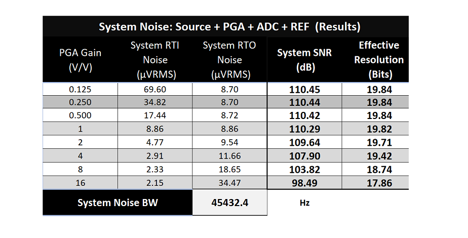
| High-Speed Mode, Sinc4, OSR = 64, Data Rate 200 kSPS |
| High-Speed Mode, Sinc4, OSR = 64, Data Rate 200 kSPS |