SLAA457B September 2013 – October 2018 MSP430F5500 , MSP430F5501 , MSP430F5502 , MSP430F5503 , MSP430F5504 , MSP430F5505 , MSP430F5506 , MSP430F5507 , MSP430F5508 , MSP430F5509 , MSP430F5510 , MSP430F5513 , MSP430F5514 , MSP430F5515 , MSP430F5517 , MSP430F5519 , MSP430F5521 , MSP430F5522 , MSP430F5524 , MSP430F5525 , MSP430F5526 , MSP430F5527 , MSP430F5528 , MSP430F5529 , MSP430F5630 , MSP430F5631 , MSP430F5632 , MSP430F5633 , MSP430F5634 , MSP430F5635 , MSP430F5636 , MSP430F5637 , MSP430F5638 , MSP430F5658 , MSP430F5659 , MSP430F6630 , MSP430F6631 , MSP430F6632 , MSP430F6633 , MSP430F6634 , MSP430F6635 , MSP430F6636 , MSP430F6637 , MSP430F6638 , MSP430F6658 , MSP430F6659 , MSP430FG6425 , MSP430FG6426 , MSP430FG6625 , MSP430FG6626
2.3 MSP430 USB Module
Features of the MSP430 USB module are as follows:
- Full-speedUSB device (12 Mbps). Full-speed is a great match for a 16-bit MCU. It facilitates communication with a USB host, with simplicity and low system cost. The module does not perform low- or high-speed transfers; it also does not function as a USB host controller.
- Supports control, interrupt, and bulk transfers. This enables support of the most popular USB device classes. (Streaming audio using isochronous transfers is not supported.)
- Eight input and eight output endpoints. The more endpoints that are supported, the more USB interfaces(logical devices) that can be implemented within a composite USB device. MSP430 MCUs have enough endpoints for as many as seven interfaces in composite (depending on the ones chosen), which is more than enough for the vast majority of USB applications.
- An integrated 3.3-V LDO, for operation directly from 5-V VBUS from the host. In some applications, this eliminates the need for an external LDO, because in addition to sourcing the MCU, the integrated LDO can be used to source the entire system, up to 12 mA. (See the device data sheet for parameters).
- An integrated D+ pullup. This pullup is the way in which a USB device tells the host it is ready to be enumerated. In contrast, some USB devices from other vendors require external circuitry to enable the pullup.
- Programmable PLL. An integrated PLL generates the 48-MHz clock needed for USB operation. The reference for this PLL comes from the MCU's XT2 oscillator. A wide variety of sources can be used for the reference.
- Integrated transceiver (PHY). There is no need to buy one separately.
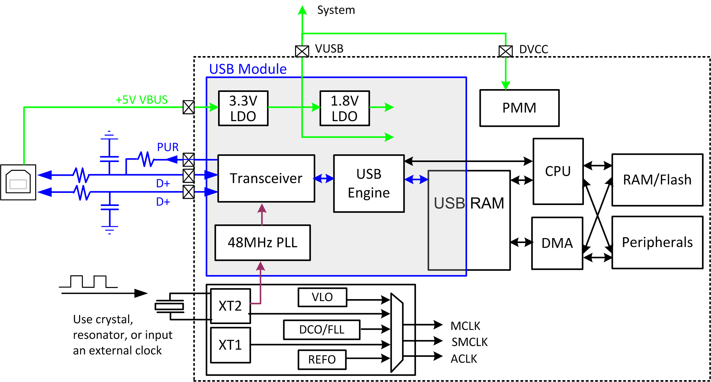
Figure 1 shows a system block diagram.
 Figure 1. MSP430 USB Block Diagram
 Parts of this block diagram are described as part of the MSP430 USB hardware reference design in Section 5. The ultimate reference for the module is the USB chapter of the MSP430F5xx and MSP430F6xx Family User's Guide.