SLAA494B May 2011 – September 2023 MSP430AFE221 , MSP430AFE222 , MSP430AFE223 , MSP430AFE231 , MSP430AFE232 , MSP430AFE233 , MSP430AFE251 , MSP430AFE252 , MSP430AFE253
- 1
- Implementation of a Single-Phase Electronic Watt-Hour Meter Using the MSP430AFE2xx
- 1 Trademarks
- 2 Introduction
- 3 Block Diagram
- 4 Hardware Implementation
- 5 Software Implementation
- 6 Energy Meter Demo
- 7 Results
- 8 Important Notes
- 9 Schematics
- 10References
- 11Revision History
5.3.4 LED Pulse Generation
In electricity meters, the energy consumed is normally measured in fraction of kilowatt-hour (kWh) pulses. This information can be used to accurately calibrate any meter or to report measurement during normal operation. To serve both of these tasks efficiently, the microcontroller must accurately generate and record the number of these pulses. It is a general requirement to generate these pulses with relatively little jitter. Although time jitters are not an indication of bad accuracy, as long as the jitter is averaged out, it can give a negative impression of the overall accuracy of the meter.
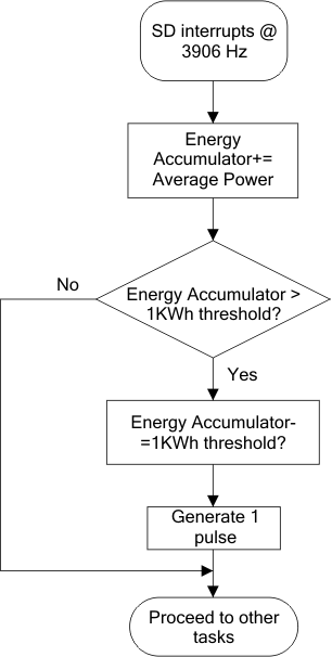
The sample code uses the average power to generate the energy pulses. The average power (calculated by the foreground process) is accumulated every SD24 interrupt. This is equivalent to converting it to energy. After the accumulated energy crosses a threshold, a pulse is generated. The amount of energy above this threshold is stored, and new energy amount is added to it in the next interrupt cycle. Because the average power tends to be a stable value, this way of generating energy pulses are very steady and free of jitter.
The threshold determines the energy tick specified by the power company and is a constant, for example, it can be in kWh. In most meters, the pulses per kWh decide this energy tick. For example, in this application, the number of pulses generated per kWh is set to 1600 for active and reactive energies. The energy tick in this case is 1 kWh/1600. Energy pulses are generated and also indicated via LEDs on the board. Port pins are toggled for the pulses with control over the pulse width for each pulse.
Figure 5-5 shows the flow diagram for pulse generation.
 Figure 5-5 Pulse Generation for Energy Indication
The average power is in units of 0.01 W and 1 kWh threshold is defined as:
1 kWh threshold = 1 / 0.01 × 1 kW × (number of interrupts/sec) × (number of seconds in 1 hour) = 100000 × 3906 × 3600 = 0x14765AAD400