SLAA600E June   2013  – January 2024


  1.   1
  2.   Abstract
  3.   Trademarks
  4. 1Introduction
    1. 1.1 Glossary
    2. 1.2 Conventions
  5. 2Implementation
    1. 2.1 Main
    2. 2.2 Application Manager
      1. 2.2.1 Boot and Application Detection
        1. 2.2.1.1 Force Bootloader Mode
        2. 2.2.1.2 Application Validation
        3. 2.2.1.3 Jump to Application
      2. 2.2.2 Vector Redirection
      3. 2.2.3 Interrupt Vectors in Flash Devices
      4. 2.2.4 Dual Image Support
        1. 2.2.4.1 Jumping to Application in Dual Image Mode
    3. 2.3 Memory Interface (MI)
      1. 2.3.1 Dual Image Support
    4. 2.4 Communication Interface (CI)
      1. 2.4.1 Physical-DataLink (PHY-DL)
        1. 2.4.1.1 I2C
          1. 2.4.1.1.1 Time-out Detection
        2. 2.4.1.2 UART
        3. 2.4.1.3 SPI
        4. 2.4.1.4 CC110x
        5. 2.4.1.5 Comm Sharing
      2. 2.4.2 NWK-APP
        1. 2.4.2.1 BSL-Based Protocol
          1. 2.4.2.1.1 Security
          2. 2.4.2.1.2 BSL-Based Protocol using CC110x
          3. 2.4.2.1.3 Examples Using I2C
          4. 2.4.2.1.4 Examples Using UART or CC110x
  6. 3Customization of MSPBoot
    1. 3.1 Predefined Customizations
  7. 4Building MSPBoot
    1. 4.1 Starting a New Project
      1. 4.1.1 Creating a New MSPBoot Project
        1. 4.1.1.1 MSPBootProjectCreator.pl
        2. 4.1.1.2 Importing Project Spec File in CCS
        3. 4.1.1.3 Modifying Generated Source Code
          1. 4.1.1.3.1 Modifying MSPBoot Main.c
          2. 4.1.1.3.2 Modifying TI_MSPBoot_Config.h
          3. 4.1.1.3.3 Modifying TI_MSPBoot_CI_PHYDL_xxxx_xxx.c
          4. 4.1.1.3.4 Modifying TI_MSPBoot_AppMgr.c
          5. 4.1.1.3.5 Modifying Application Main.c
          6. 4.1.1.3.6 Modifying TI_MSPBoot_Mgr_Vectors_xxxx.c
      2. 4.1.2 Loading Application Code With MSPBoot
        1. 4.1.2.1 Convert Application Output Images
    2. 4.2 Examples
      1. 4.2.1 LaunchPad Development Kit Hardware
      2. 4.2.2 CC110x Hardware
      3. 4.2.3 Building the Target Project
      4. 4.2.4 Building the Host Project
      5. 4.2.5 Running the Examples
  8. 5References
  9. 6Revision History

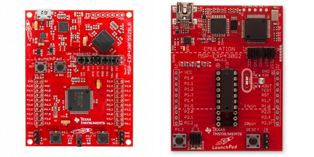
LaunchPad Development Kit Hardware

GUID-AABFFAB2-F898-4D8D-A67F-CC0E9336E279-low.jpg
P2.0 is not connected to LED2 by default in MSP-EXP430G2. An external connection can be added for demo purposes when using I2C communication
Jumper J5 that connects P1.6 to LED2 must be removed in MSP-EXP430G2 when using I2C communication.
Figure 4-4 Target Boards: MSP-EXP430F5529 and MSP-EXP430G2

The bootloader and demo applications use the same LED (LED1 and LED2) notations across all variants of the LaunchPad development kits. The pin assignments that correspond to these I/O peripherals are different for each board derivative. For each use, the examples have been designed so that the host and target LaunchPad development kits can be the same derivative, although there are examples and this can be modified for different configurations if desired.