SLAA600E June   2013  – January 2024


  1.   1
  2.   Abstract
  3.   Trademarks
  4. 1Introduction
    1. 1.1 Glossary
    2. 1.2 Conventions
  5. 2Implementation
    1. 2.1 Main
    2. 2.2 Application Manager
      1. 2.2.1 Boot and Application Detection
        1. 2.2.1.1 Force Bootloader Mode
        2. 2.2.1.2 Application Validation
        3. 2.2.1.3 Jump to Application
      2. 2.2.2 Vector Redirection
      3. 2.2.3 Interrupt Vectors in Flash Devices
      4. 2.2.4 Dual Image Support
        1. 2.2.4.1 Jumping to Application in Dual Image Mode
    3. 2.3 Memory Interface (MI)
      1. 2.3.1 Dual Image Support
    4. 2.4 Communication Interface (CI)
      1. 2.4.1 Physical-DataLink (PHY-DL)
        1. 2.4.1.1 I2C
          1. 2.4.1.1.1 Time-out Detection
        2. 2.4.1.2 UART
        3. 2.4.1.3 SPI
        4. 2.4.1.4 CC110x
        5. 2.4.1.5 Comm Sharing
      2. 2.4.2 NWK-APP
        1. 2.4.2.1 BSL-Based Protocol
          1. 2.4.2.1.1 Security
          2. 2.4.2.1.2 BSL-Based Protocol using CC110x
          3. 2.4.2.1.3 Examples Using I2C
          4. 2.4.2.1.4 Examples Using UART or CC110x
  6. 3Customization of MSPBoot
    1. 3.1 Predefined Customizations
  7. 4Building MSPBoot
    1. 4.1 Starting a New Project
      1. 4.1.1 Creating a New MSPBoot Project
        1. 4.1.1.1 MSPBootProjectCreator.pl
        2. 4.1.1.2 Importing Project Spec File in CCS
        3. 4.1.1.3 Modifying Generated Source Code
          1. 4.1.1.3.1 Modifying MSPBoot Main.c
          2. 4.1.1.3.2 Modifying TI_MSPBoot_Config.h
          3. 4.1.1.3.3 Modifying TI_MSPBoot_CI_PHYDL_xxxx_xxx.c
          4. 4.1.1.3.4 Modifying TI_MSPBoot_AppMgr.c
          5. 4.1.1.3.5 Modifying Application Main.c
          6. 4.1.1.3.6 Modifying TI_MSPBoot_Mgr_Vectors_xxxx.c
      2. 4.1.2 Loading Application Code With MSPBoot
        1. 4.1.2.1 Convert Application Output Images
    2. 4.2 Examples
      1. 4.2.1 LaunchPad Development Kit Hardware
      2. 4.2.2 CC110x Hardware
      3. 4.2.3 Building the Target Project
      4. 4.2.4 Building the Host Project
      5. 4.2.5 Running the Examples
  8. 5References
  9. 6Revision History

Interrupt Vectors in Flash Devices

The minimum size for a flash erase is a segment, which is 512 bytes in MSP430 MCUs. Given this consideration, the whole interrupt table is protected from erases. To allow interrupts on an application level, a software vector redirection method is implemented to fix the contents of the default vector table and point to a proxy table that resides in application space.

Figure 2-5 shows the concept behind this implementation:
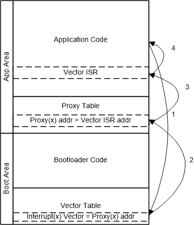
GUID-82160F01-BEE6-4AEB-B93B-C75D5E71B357-low.gifFigure 2-5 Vector Redirection Implementation
  1. The application receives an interrupt request, the current address is pushed into the stack, and the CPU fetches the address from the vector table.
  2. The vector table contains the address of the proxy location for each interrupt. The CPU fetches the address of the corresponding entry in the proxy table and jumps to it.
  3. The proxy table contains branch instructions (BRA) followed by the actual address of each ISR. The CPU executes the BRA instruction and jumps to the corresponding application vector ISR.
  4. Upon completion of the ISR, the RETI instruction is executed, and the previous address is popped from the stack.

This process is almost transparent for the implementation of an application, but it is important to note that there is added latency due to the additional jump from the proxy table to the application ISR.

Application examples that show how to implement interrupts are included in the sample code to demonstrate this functionality.

Note that some MSP430 MCUs support redirecting vectors to RAM in hardware (SYSRIVECT), which could be a good alternative for devices with sufficient RAM.