SLAA976 October 2020 MSP430FR5041 , MSP430FR5043 , MSP430FR6005 , MSP430FR6007 , MSP430FR6041 , MSP430FR6043 , MSP430FR6045 , MSP430FR6047
1 Introduction
Existing oxygen concentration sensors are typically based on electrochemical or Zirconium technologies. While being a mature technology, recent technological trends to increase integration, reduce size, and lower power consumption are making equipment manufacturers look into other implementations that better satisfy these new requirements. Ultrasonic sensors offer long lifespan and do not require replacement or re-calibration every 1-3 years like electrochemical or Zirconium sensors. This technology is not limited to just Oxygen sensing, it can also be used for other gases such as Nitrogen, Hydrogen, Nitrous Oxide, Carbon Dioxide, Argon, and Helium. These sensors are commonly found in ventilators, concentrators, and combustion monitors.
TI’s ultrasonic sensing solution with the MSP430FR6043 brings high accuracy at flow rates ranging from less than 1LPM to greater than 190LPM, with measurement periods of less than 10 ms to bring precision to pulse oxygen applications.
Ultrasonic concentration sensing relies on the relationship that exists between the sonic velocity of a gas medium and its molar weight (see Equation 3). This principle can be extrapolated to a binary gas composition. If the molar weights of the two gases present are known (simplified as oxygen and nitrogen in this application), the volume concentration of each gas can be extracted from the specific sonic speed of the sample mixture (see Equation 4).
|
C = Speed of sound in gas medium |
MO2 = Molar weight of ~ 32 |
|
k = Specific heat ratio ~ 1.4 for and air |
MN = Molar weight of ~ 28 |
|
R = Universal gas constant |
ƿ = Volume concentration |
|
T = Temperature ~ 295.85 K in this example |
L = Sensor distance ~ 4.4 cm in this example |
|
M = Molar weight of gas mixture |
V = Velocity of gas flow |
The speed of sound in a binary gas mixture is determined by using the TOF equations (1). For low flow rate applications, such as those in oxygen concentrators or CPAP machines with 1LPM – 15LPM of flow, the velocity of gas flow V can be ignored. In these cases, C >> V.
TI’s ultrasonic sensing technology comprises an analog-to-digital converter (ADC)-based cross-correlation approach that uses frequency information to determine the ultrasonic time of flight with much higher accuracy than existing TDC based techniques. For more information about how this unique algorithm works and TI’s Ultrasonic Sensing Subsystem (USS), see TIDM-02003.
TI’s Ultrasonic Sensing Subsystem enables a single chip solution which can be connected to ultrasonic transducers along with an op-amp and mux for high resolution flow measurements. TI’s USS is integrated with a Low Energy Accelerator (LEA) and MSP CPU to enable autonomous low power operation with an average current consumption of less than 20 μA (at one measurement per second).
TI’s Ultrasonic Sensing Subsystem (depicted in Figure 1-1) comprises a Programmable Pulse Generator (PPG) and a High-Speed Sigma Delta analog to digital converter with a Programmable Gain Amplifier (PGA) that can autonomously excite and capture ultrasonic waveforms for subsequent processing via an integrated Low Energy Accelerator (LEA).
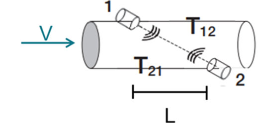
 Figure 1-1 Ultrasonic Tube
This ultrasonic subsystem (depicted in Figure 1-1) first excites an “upstream” transducer connected to CH0_OUT while capturing the waveform from a “downstream” transducer connected to CH0_IN. The ultrasonic subsystem subsequently excites the “downstream” transducer connected to CH1_OUT while capturing the waveform from the “upstream” transducer connected to CH1_IN. These waveforms are then processed by the Low Energy Accelerator to determine the difference between the upstream and downstream Time of Flight.