SLAAE64 may 2023 AFE58JD48 , DAC81001 , DAC8801 , DAC8830 , OPA2210 , REF5010 , REF5040 , THS4130
2.2.3 PSpice-TI Simulation
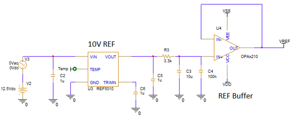
Download the PSpice-TI simulation models for the relevant components from https://www.ti.com. The reference section of the circuit shown in Figure 2-6 can be simulated in PSpice-TI (shown in Figure 2-7) and noise analysis can be performed.

Figure 2-7 PSpice-TI Simulation for Reference Circuit (in previous image)
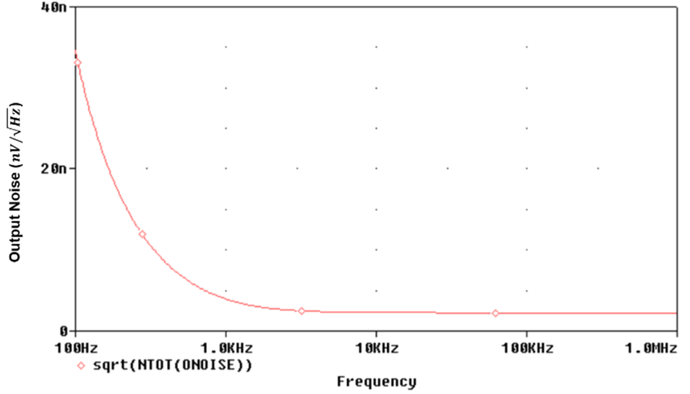
This noise is bandwidth-limited using the resistor-capacitor (R-C) filter at the output. Figure 2-8 shows the simulated results for the noise contribution from REF5010. Figure 2-9 shows the modeled noise contribution of the DAC8801 at the maximum output current.

Figure 2-8 Noise Contribution From the Reference Circuit

Figure 2-9 Noise Model for the DAC8801
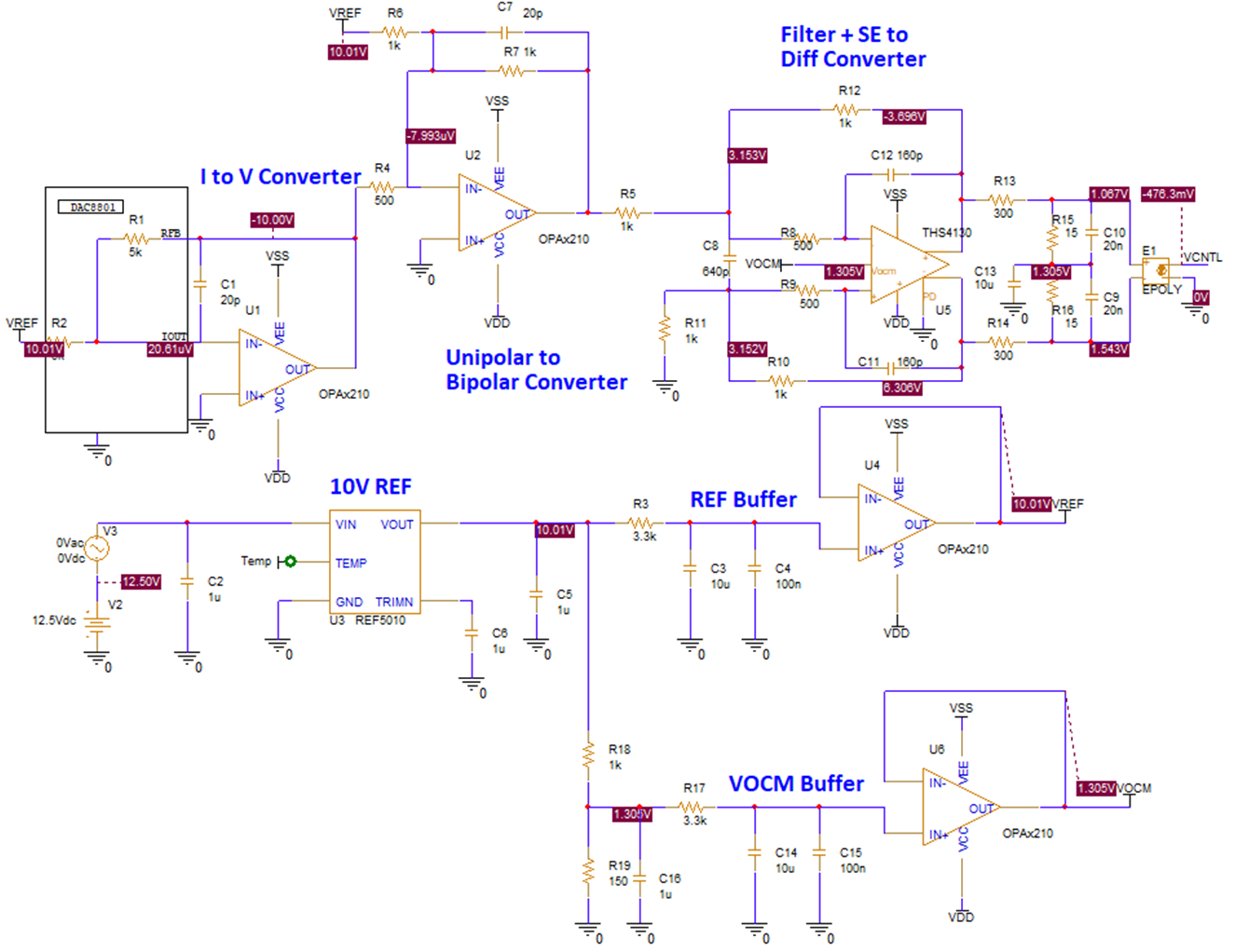
Figure 2-10 shows the PSpice -TI simulation for the entire circuit.

Figure 2-10 PSpice-TI Simulation of the Proposal 2 VCNTL Drive Circuit
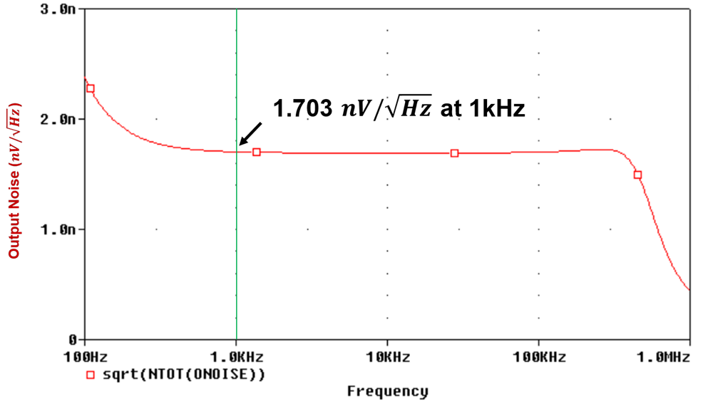
Figure 2-11 shows the noise contribution of the proposal 2 circuit, the output noise of 1.703 nV/√Hz at 1 kHz indicates that such a drive circuit can drive about 64 to 128 channels simultaneously.

Figure 2-11 Noise Contribution of the Proposal 2 Circuit