SLUAA69 July   2020  – MONTH  TPS548D22


  1.   Trademarks
  2. 1Introduction
    1. 1.1 LED Driver Methods
    2. 1.2 Power Supply Solutions for Common-Cathode LED Display
  3. 2Principle of Synchronous Buck with Sinking Current Application
  4. 3 Design Considerations and Analysis
    1. 3.1 Choose an IC with Sufficient Current Sinking
    2. 3.2 Choose IC Supporting Negative OCP
    3. 3.3 Choose an IC Supporting Pre-Bias Startup
    4. 3.4 Analysis of System Startup
  5. 4 TI Devices and Functionalities
    1. 4.1 Negative OCP Functionality
    2. 4.2 Hiccup Mode and Latch-off Mode
    3. 4.3 UVP and OVP Functionality
  6. 5 TI Solution
  7. 6 Bench Test and Result
    1. 6.1 Bench Test Configuration
    2. 6.2 Startup Waveforms and Behaviors Analysis Overview
    3. 6.3 Startup Waveforms and Behaviors Analysis at the First OVP
    4. 6.4 Startup Waveforms and Behaviors Analysis after the First OVP
    5. 6.5 Waveforms and Behaviors Analysis of Startup Solution with Lazy Loading
  8. 7 Conclusion
  9. 8References

Bench Test Configuration

Figure 6-1 shows the bench test configuration of TPS548D22 with sinking current application. The power supply used in this configuration was limited to 8-A current. Therefore this test is not able to validate the 30 A full load (Rload = 3.2 V/30 A = 0.107 ohm) condition. However, an approximate 9.3-A load (Rload = 3.2 V/0.34 ohm = 9.3 A) is sufficient to verify the feasibility of TPS548D22 with a current sink application. Note that the output voltage of the DC power supply is set at 4.7 V. This is higher than the 4.2-V input voltage due to resistive loss in the cabling.
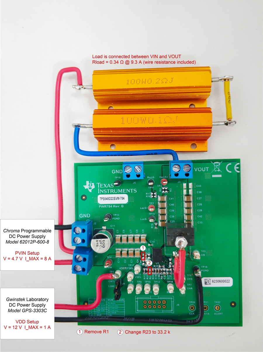
GUID-20200604-SS0I-R5T7-THMR-8DFLP3B1WN5Z-low.jpg Figure 6-1 Bench Test Configuration of TPS548D22 with Sinking Current Application