SLUU194A May   2004  – March 2022 TPS51020


  1.   Trademarks
  2. 1Introduction
  3. 2Electrical Performance Specifications
    1. 2.1 Performance Specification Summary
  4. 3TPS51020EVM-001 Circuit Module Schematic
  5. 4Test Setup and Results
    1. 4.1 Test Setup
    2. 4.2 Power Up and Power Down
    3. 4.3 Efficiency and Power Loss
    4. 4.4 Output Ripple
    5. 4.5 Load Transient
    6. 4.6 Loop Characteristics
  6. 5Assembly Drawing and PCB Layout
  7. 6Circuit Module List of Materials
  8. 7References
  9. 8Revision History

Loop Characteristics

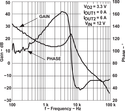
Figure 4-9 and Figure 4-10 show the bode plot of each channel. The crossover frequency is approximately 14 kHz and the phase margin is 32° for Channel 1 when the output is 5 V and 6 A. Channel 2 shows a 15-kHz crossover frequency and a 41° phase margin.
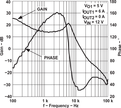
GUID-20220310-SS0I-M56X-J9DG-VMVXKMCDWPKC-low.gifFigure 4-9 Channel 1 Bode Plot
GUID-20220310-SS0I-BRWF-TR5F-KK1MXT680CQG-low.gifFigure 4-10 Channel 2 Bode Plot