SLVA528D September 2012 – August 2021 TPS65381-Q1 , TPS65381A-Q1
- Trademarks
- 1Introduction
- 2Product Overview
- 3Development Process for Management of Systematic Faults
- 4TPS65381x-Q1 Product Architecture for Management of Random Faults
-
5TPS65381x-Q1 Architecture Safety Mechanisms and Assumptions of Use
- 5.1 Power Supply
- 5.2 Regulated Supplies
- 5.3
Diagnostic, Monitoring, and Protection Functions
- 5.3.1 External MCU Fault Detection and Management
- 5.3.2 Voltage Monitor (VMON)
- 5.3.3 Loss-of-Clock Monitor (LCMON)
- 5.3.4 Junction Temperature Monitoring and Current Limiting
- 5.3.5 Analog and Digital MUX (AMUX and DMUX) and Diagnostic Output Pin (DIAG_OUT)
- 5.3.6 Analog Built-In Self-Test (ABIST)
- 5.3.7 Logic Built-In Self-Test (LBIST)
- 5.3.8 Device Configuration Register Protection
- 6Application Diagrams
- 7TPS65381x-Q1 as Safety Element out of Context (SEooC)
- 8Revision History
5.3.1.1 External MCU Error Signal Monitor (MCU ESM)
This block monitors the external MCU error conditions signaled to the TPS65381x-Q1 device on the ERROR/WDI input pin. The monitor has two configuration options for use with microcontrollers with dual-core lockstep (LS) or loosely coupled (LC) architectures:
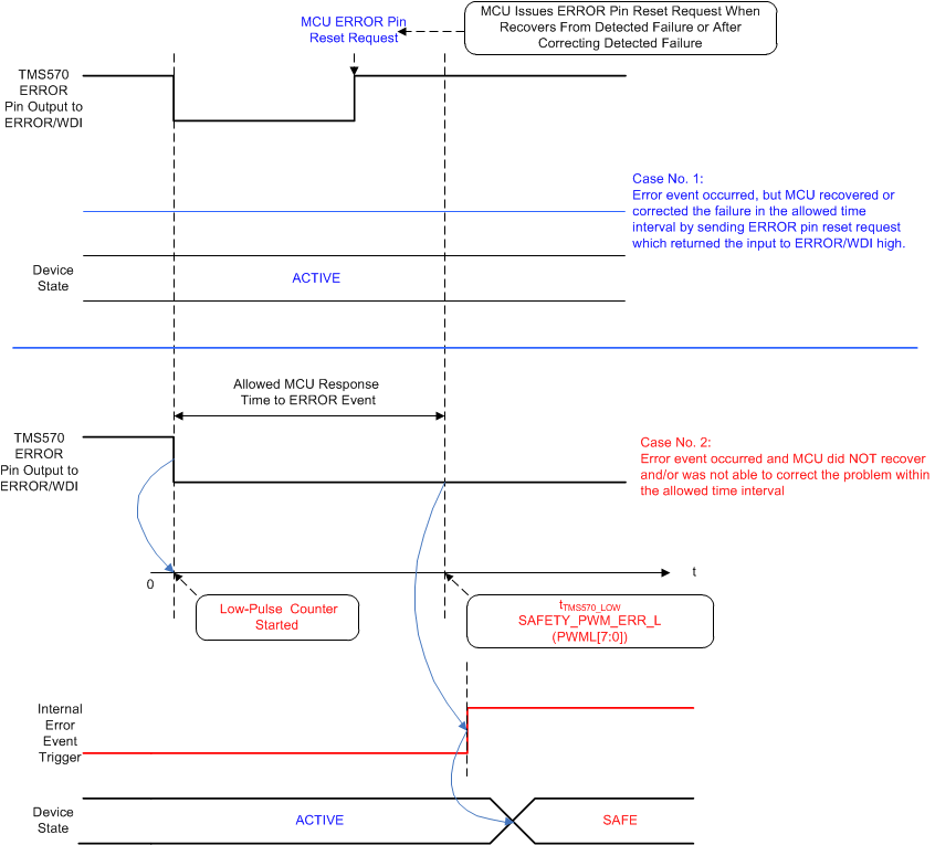
- TMS570 mode: Detecting a low pulse signal with programmable expected low pulse duration.
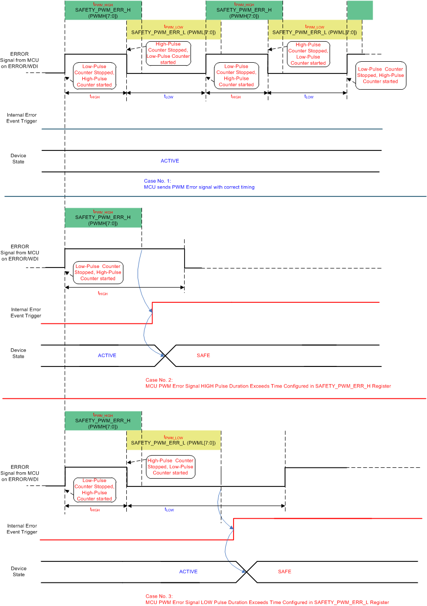
- PWM mode: Detecting a PWM signal with programmable frequency and duty cycle.
The ERROR_CFG bit in the SAFETY_FUNC_CFG register controls the operating mode. The SAFETY_ERR_PWM_L register sets the expected low signaling duration for TMS570 mode and low pulse duration for PWM mode. The SAFETY_ERR_PWM_H register sets the expected PWM high pulse duration in PWM mode.
Logic BIST (LBIST) adds diagnostic coverage to the module. The MCU ESM can only be used when the watchdog is operated in Q & A mode.
 Figure 5-2 Error Detection Case Scenarios in TMS570 Mode
 Figure 5-3 Error Detection Case Scenarios in PWM Mode