SLVA833D October 2016 – May 2021 TPS2660 , TPS2662 , TPS2663
- Trademarks
- 1 Surge Test (IEC 61000-4-5)
- 2 EFuse Solution for Surge Protection
- 3 EFuse Solution Schematic for Surge Protection
- 4 Circuit Performance for Surge Tests
- 5 EFT Test (IEC 61000-4-4)
- 6 EFuse Solution Schematic for EFT protection
- 7 Circuit Performance for EFT Tests
- 8 Power-Fail Test (IEC 61000-4-29)
- 9 EFuse Solution Schematic for Power-Fail Applications
- 10Circuit Performance for Power-Fail Tests
- 11EFT, Surge and Power-Fail Test Setup
- 12Conclusion
- 13References
- 14Revision History
10 Circuit Performance for Power-Fail Tests
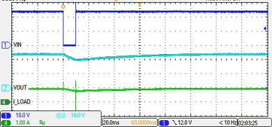
Figure 10-1 shows the performance of the TPS2660 for 10 ms supply interruption. During power-fail, the output bulk capacitor supplies the system load. When supply voltage resumes, the TPS2660 charges the output capacitance with the current limit.
 Figure 10-1 10 ms Input Power-Fail at
VIN = 24 V, Load = 24 Ω (IEC 61000-4-29 Level -1)
Figure 10-1 10 ms Input Power-Fail at
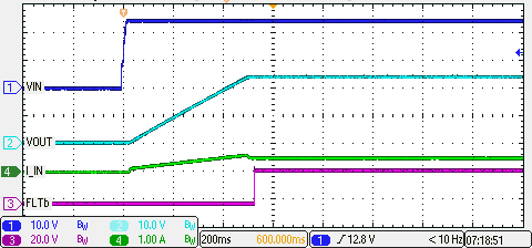
VIN = 24 V, Load = 24 Ω (IEC 61000-4-29 Level -1)Figure 10-2 shows the startup of the TPS2660 when the supply voltage is ramped up. The circuit limits charging current to the bulk capacitor and simultaneously provides the required load current.
 Figure 10-2 Startup With VIN =
24 V and Load = 48 Ω