SLVAED3A July 2019 – April 2024 TPS568230
4 Transient Response
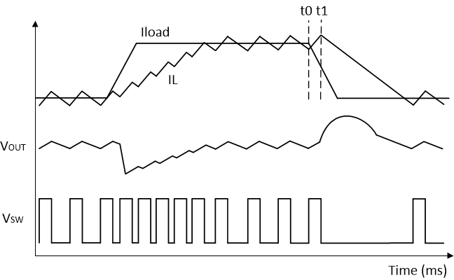
The load transient is stringent in some high-end. The D-CAP3 transient response is very quick and output transients are usually small. There are two key elements that may influence load transient. One element is the load step size and the transient slew rate. The other elements are output capacitor/inductor and switching frequency. The output LC should be designed to meet the transient requirement. Figure 4-1 shows how D-CAP3 topology works in a load transient case[4].
 Figure 4-1 Load Transient Response of
D-CAP3 Converter
Figure 4-1 Load Transient Response of
D-CAP3 ConverterDuring load step-up: The D-CAP3-based converter reacts with reducing off-time response until the minimum off time is reached while maintaining the constant on time as shown in Figure 4-1. It takes a relatively shorter time for the inductor to catch up the load step due to the absence of the error amplifier. The output undershoot is mainly impacted by loop response time, output inductance, capacitance, and minimum off time.
During load step-down: The converter stops switching when the output voltage becomes bigger than the reference voltage. There could be some delay from load release to non-switching due to the onset of the on-time timer. t0–t1 in Figure 4-1 shows the delay period. Two delays are commonly found in D-CAP3 control: one is the comparator delay and the other is on time delay. In any D-CAP3 control, the on time is always constant. If the load release occurs during the very beginning of the on time, the on time must complete its pre-programmed duration before being turned off. The worst-case delay could be expected to be 1 × Ton as Ton = D × 1 / fsw. The delay time directly affects the energy delivered to the output capacitor so the output overshoot is mainly dominated by output inductor/capacitor and constant on time. The higher the frequency, the shorter the Ton, which is good for overshoot.
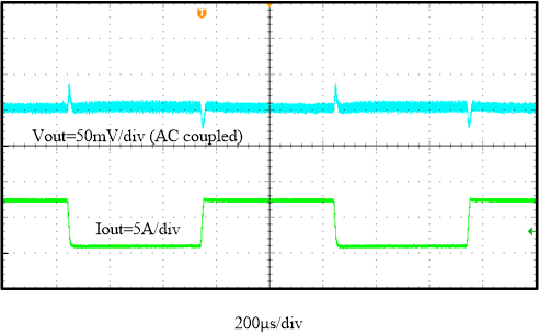
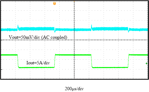
Figure 4-2 and Figure 4-3 show the load transient test results under the condition in Table 2-1. Load transient from 0.8 A to 7.2 A with a 2.5 A/µs slew rate. The overshoot/undershoot are 35 mV/-27 mV under 600 kHz and 25 mV/-15 mV under 1000 kHz. The undershoot of 1000 kHz is better even through using a smaller output capacitor. Because the loop response speed of 1000 kHz mode is faster than 600 kHz mode since the smaller output inductor and capacitor can be used in higher frequency. Besides, the overshoot under 1 MHz is better than 600 kHz as the Ton is relatively shorter when 1000 kHz mode is selected.
 Figure 4-2 Load Transient,
FSW = 600 kHz
 Figure 4-3 Load Transient,
FSW = 1000 kHz