SLVAER4 August 2020 – MONTH TPS61022
3 Loop Stability, Feedforward Capacitor Selection
To fully utilize the supercap energy and extend the backup power time, the TPS61022 device is used to regulate until the supercap voltage discharges to as low as 0.5 V. For low VIN < 1.5 V condition, TI recommends using a large output capacitance at TPS61022 output to lower the crossover frequency because the right half plane zero (RHPZ) frequency reduces with decreasing VIN.

where
Rout = output load resistor
D = duty cycle
L = inductance
For instance, when VIN = 0.7 V, VOUT = 3.3 V, IOUT = 0.8 A, L = 1 μH, fRHPZ = 29.5 kHz. It is generally accepted that the loop gain crossover no higher than the lower of either 1/10 of the switching frequency, ƒSW, or 1/5 of the RHPZ frequency, fRHPZ.
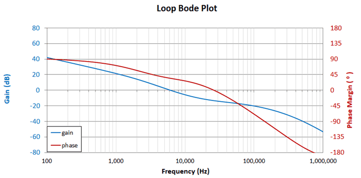
The TPS61022 Calculation Tool helps calculate the loop bode plot with 30-μF effective output capacitance by inputting the previously listed parameters. Figure 3-1 shows the crossover frequency is 6.2 kHz and phase margin is only 34.5°, which causes an unstable loop issue.
 Figure 3-1 Bode Plot in VIN = 0.7 V,
VOUT = 3.3 V, IOUT = 0.8 A, COUT= 30 µF
Condition
Figure 3-1 Bode Plot in VIN = 0.7 V,
VOUT = 3.3 V, IOUT = 0.8 A, COUT= 30 µF
ConditionTherefore, to set the loop crossover frequency fc lower than 1/5 of the RHPZ frequency, a large output capacitance can decrease the crossover frequency. In the meantime, a feedforward capacitor (C3 in Figure 2-1) and resistor R3 in parallel with upper feedback resistor R1 introduces a pair of zero fFFZ and pole fZZP in the loop transfer function. By setting the proper zero frequency fFFZ, the feedforward capacitor can increase the phase margin to improve the loop stability. The pole fZZP can increase the phase margin by adjusting R3 resistance by Equation 2 and Equation 3.


Therefore, the ESR of the output capacitor creates a zero frequency:

Big ESR leads to a small zero fESR into the loop. Combining with the feedforward capacitor zero fFFZ, the crossover frequency fc will be increased to very high and phase margin is not big enough. Therefore, it is recommended to put a low ESR (< 50 mΩ) 100-µF aluminum electrolytic capacitor or aluminum polymer capacitor at the TPS61022 output. TI recommends setting the zero frequency fFFZ to 2 kHz. R3 is set to 2 kΩ in default, which helps eliminate the output AC noise coupled to the FB pin.