SLVUBX1 December 2020 TPS63810
6 Graphical User Interface (GUI)
A graphical user interface (GUI) is available from dev.ti.com in the software gallery, allowing a simple and convenient interface to the BOOSTXL-TECDRV BoosterPack through the MSP-EXP432P401R LaunchPad. A standalone version of the GUI can be downloaded or the web-based version can be used directly from the browser.
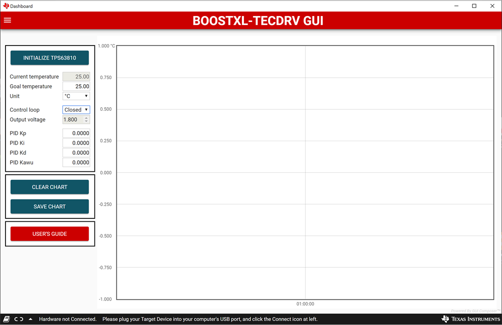
This section gives an overview of the BOOSTXL-TECDRV GUI. Figure 6-1 shows the layout of the BOOSTXL-TECDRV GUI. The left portion of the GUI is used to control and monitor the system operation. The right part of the GUI shows a time chart of the measured temperature.
 Figure 6-1 GUI Interface Window
Upon startup, the GUI automatically connects to the EVM. If not, click on the Connect button in the lower left corner of the GUI window.
To select the correct serial COM port for communication with the LaunchPad, the desired port can be selected from the Options drop down menu in the upper left corner by selecting Serial Port.
Once the communication is established and the hardware is connected, the temperature control can be started by clicking on the Initialize TPS63810 button. This will turn the TPS63810 output on, and turn on the closed loop control by starting the PID controller in the LaunchPad. In the left side of the GUI interface, the goal temperature can be set, and the actual temperature and the current output voltage of the TPS63810 can be monitored. Upon initialization, the GUI will read the default PID parameters set in the firmware and display them. If needed, these PID parameters can be changed in real time to tune the response of the system.
Alternatively, the system can be run open loop by selecting OPEN in the Control loop drop-box. In this mode the goal temperature is ignored. Instead, the output voltage of the TPS63810 can be changed manually. This can be used to create a step response for tuning the system for the particular TEC/sensor combination being used. This is explained in more details in Section 7.
Clicking the Clear chart button clears the temperature time chart, whereas the Save chart button saves the currently displayed chart in CSV format. Clicking the User’s guide button leads to the online version of this user’s guide.