SLYT800B december 2020 – december 2020 LM25180 , LM25183 , LM25184 , LM5180 , LM5181
2 A PSR Flyback DC/DC Converter with Multimode Control
Figure 1 shows the schematic of a PSR flyback converter[3] with integrated primary switch and loop-compensation components. The converter supports magnetically-sensed regulation of the output voltage through the transformer’s primary winding. Equation 1 gives the output voltage setpoint:
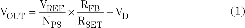
where NPS is the primary-to-secondary transformer turns ratio, VREF is the internal bandgap reference voltage, and VD is the flyback diode drop (at close to zero current).
 Figure 1 Typical Schematic of an
Auxless PSR Flyback Converter
Figure 1 Typical Schematic of an
Auxless PSR Flyback ConverterUsing a variable switching-frequency-control law with peak current-mode control, the converter operates in boundary (BCM) or discontinuous (DCM) conduction mode depending on the load current, as depicted in Figure 2.[4] Modulating the switching frequency and peak primary current amplitude helps maintain high efficiency across wide operating ranges of load and line.
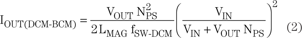
More specifically, the converter operates in BCM at heavy loads, and the primary switch turns on with a resonant-half-period delay after switch voltage-knee detection (core reset) to achieve a quasi-resonant switching transition. As shown in Figure 2, the switching frequency in BCM increases as the load current decreases. To prevent high-frequency operation at medium load, the mode changes from BCM to DCM such that the switching frequency remains constant at its maximum value (350 kHz in this example). Equation 2 gives the critical output current at the DCM-BCM boundary.
Operation at light load changes to frequency-foldback mode (FFM), which is effectively DCM with a variable switching frequency and constant peak current. Because magnetic regulation relies on sensing the output voltage during switching cycles, it is necessary to maintain a certain minimum switching frequency at no load to continue sensing the output voltage (12 kHz in this example).
As shown in Figure 2, BCM has a lower switching frequency and a higher peak current than DCM. As such, BCM dictates the output capacitor sizing for a given ripple voltage specification. Figure 3 shows the secondary-side waveforms in BCM.
 Figure 2 Switching Frequency and
Primary Peak Current vs. Load Current for the LM25184
Figure 2 Switching Frequency and
Primary Peak Current vs. Load Current for the LM25184 Figure 3 Idealized Current Waveforms of
a Flyback Converter in BCM
Figure 3 Idealized Current Waveforms of
a Flyback Converter in BCM