SLYT800B december 2020 – december 2020 LM25180 , LM25183 , LM25184 , LM5180 , LM5181
3 Output Capacitor Sizing for Voltage Ripple
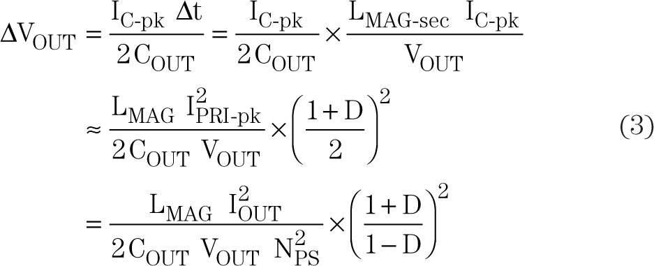
Based on the waveforms in Figure 3, Equation 3 expresses the output capacitor peak-to-peak ripple voltage, ∆VOUT, in BCM:
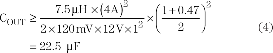
Using the circuit values in Figure 1, Equation 4 gives the required capacitance for 1% ripple on a 12-V output:
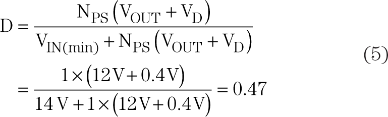
Equation 5 defines the worst-case condition at maximum duty cycle (corresponding to the minimum input voltage):
Equation 6 gives the output capacitor RMS current:
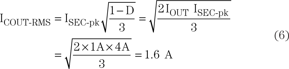
Figure 4 shows the effective capacitance versus voltage and temperature of a 22-µF, 25-V multilayer ceramic capacitor (MLCC) from Murata.[5] Even though the name-plate capacitance is 22 µF, the effective value is 9.1 µF at 25°C and 7.2 µF at –40°C when applying a DC bias of 12 V. Meeting the ripple voltage specification therefore requires three such capacitors in parallel. The equivalent series resistance (ESR) of each MLCC is approximately 3 mΩ within the frequency range of interest, and represents a negligible contribution to output ripple.
 Figure 4 MLCC Plots for a 22-µF, 25-V, 1210,
X7R Capacitor
Figure 4 MLCC Plots for a 22-µF, 25-V, 1210,
X7R CapacitorFigure 5 shows the simulated primary and secondary currents, the primary switch voltage, and the output capacitor ripple voltage at input voltages of 14 V (BCM) and 42 V (DCM) with an effective output capacitance of 22 µF. For simplicity, the oscillatory effects of transformer parasitic leakage inductance were not included.
The × symbols in Figure 5 mark the PSR sampling instants on the output voltage waveform. Sampling occurs at an instantaneous output voltage of 12 V close to the peak of the ripple waveform, but the DC output voltage is slightly lower given the total ripple amplitude.