SNIU051 March 2023
3.2.2 Data Capture Tab
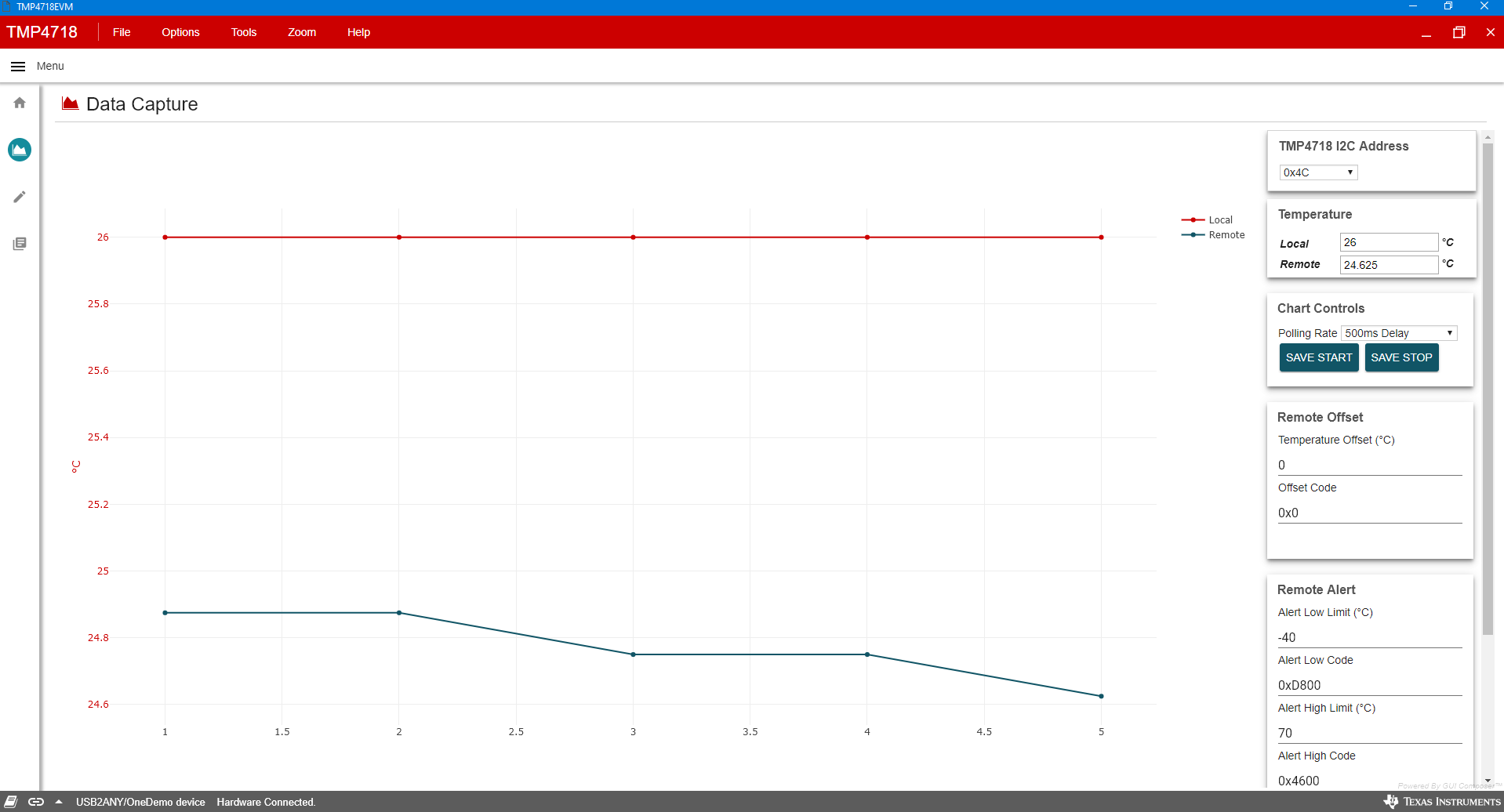
The Data Capture tab reports the temperature from the TMP4718 device and the remote temperature sensor included on the EVM.
 Figure 3-3 Data Capture Tab
The top right panel of the Data Capture tab allows the user to configure the device address. See #GUID-E4CA8A23-3CAC-48B9-BDFC-3EE97EBAF4EC/GUID-B42CD07C-6A42-4CD8-A7C0-B569DDE305E8 for the device orderables and respective addresses. The evaluation board is populated with TMP4718ADGKR, which has I2C address 0x4C.
| PART NUMBER | I2C ADDRESS |
|---|---|
| TMP4718ADGKR | 0x4C |
| TMP4718BDGKR | 0x4D |
The current Local and Remote temperature values are read out in °C. The user can also control the polling rate and filestream save from the Data Capture tab. Offset and alert controls allow the user to input a value for these registers in both C and hex. This feature allows for simple and quick control of the register map settings.