SNLA435A September 2023 – January 2024 DS320PR1601 , DS320PR410 , DS320PR810
3.2 How Does Eye Scan Work?
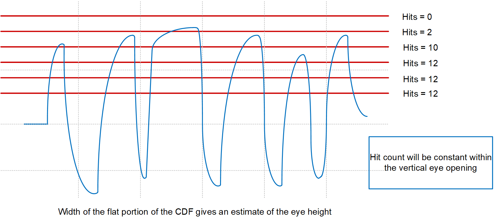
Inter-symbol interference (ISI) due to different data patterns and transmission lines can cause changes in vertical and horizontal eye openings. Thus, when monitoring PCIe link quality and stability with Eye Scan, normalizing techniques must be considered. Eye Scan works by counting the number signal hits at the PCIe redriver transmitter using a 64-level programmable DAC. The horizontal level of this DAC is swept for each of the DAC's 64 steps across a programmable range of voltage, limiting the incoming signal to the redriver’s internal Eye Scan counter. This can be visualized using Figure 3-1.

Figure 3-1 Eye Scan DAC and Hit Counts
At each DAC level, the number of signal hits is counted based upon the intersection of the signal with the DAC’s voltage level, represented by horizontal lines in Figure 3-2. For each selected DAC level, the number of hit counts accumulate in a volatile redriver register and can then be stored in external memory as the DAC level is swept over the programmable DAC voltage range. The approach of Eye Scan is further detailed in Figure 3-2.

Figure 3-2 Eye Scan Hit Count Approach
To fully understand the concept of Eye Scan, the statistical concept of a Cumulative Distributive Function (CDF) must be introduced. A CDF of a real-valued random variable X is the function given by
Where the right side represents the probability that the random variable X takes on a value less than or equal to x. In this case, the random variable X is normally distributed with mean μ and standard deviation σ, that is
We can assume that the hit events of the high-speed waveform is normally distributed, thus a CDF of a normally distributed random variable X can be used when approximating the vertical eye opening at the redriver.
Using the above definition and CDF, the following conclusions can be made regarding hit count accumulation:
- A random bit pattern causes random vertical eye openings based on transmission media loss characteristics, thus multiple samples of the waveform are taken when accumulating hit counts.
- Zero hit counts accumulated at a DAC voltage level means that the voltage level is outside of the top or bottom of the vertical eye opening.
- Constant high hit counts accumulated at a DAC voltage level means that the voltage level is within the vertical eye opening.
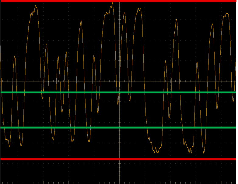
An example of these conclusions is shown in Figure 3-3. The waveform is captured from an oscilloscope, where the top and bottom of the eye diagram are bounded by zero hit count values, while areas internal to the vertical eye opening are accumulated as near-constant hit count values.

Figure 3-3 Zero Hit Counts (Red) vs. Constant Hit Counts (Green)