SNLA435A September 2023 – January 2024 DS320PR1601 , DS320PR410 , DS320PR810
4.1 Eye Scan Application: PCIe Compliance
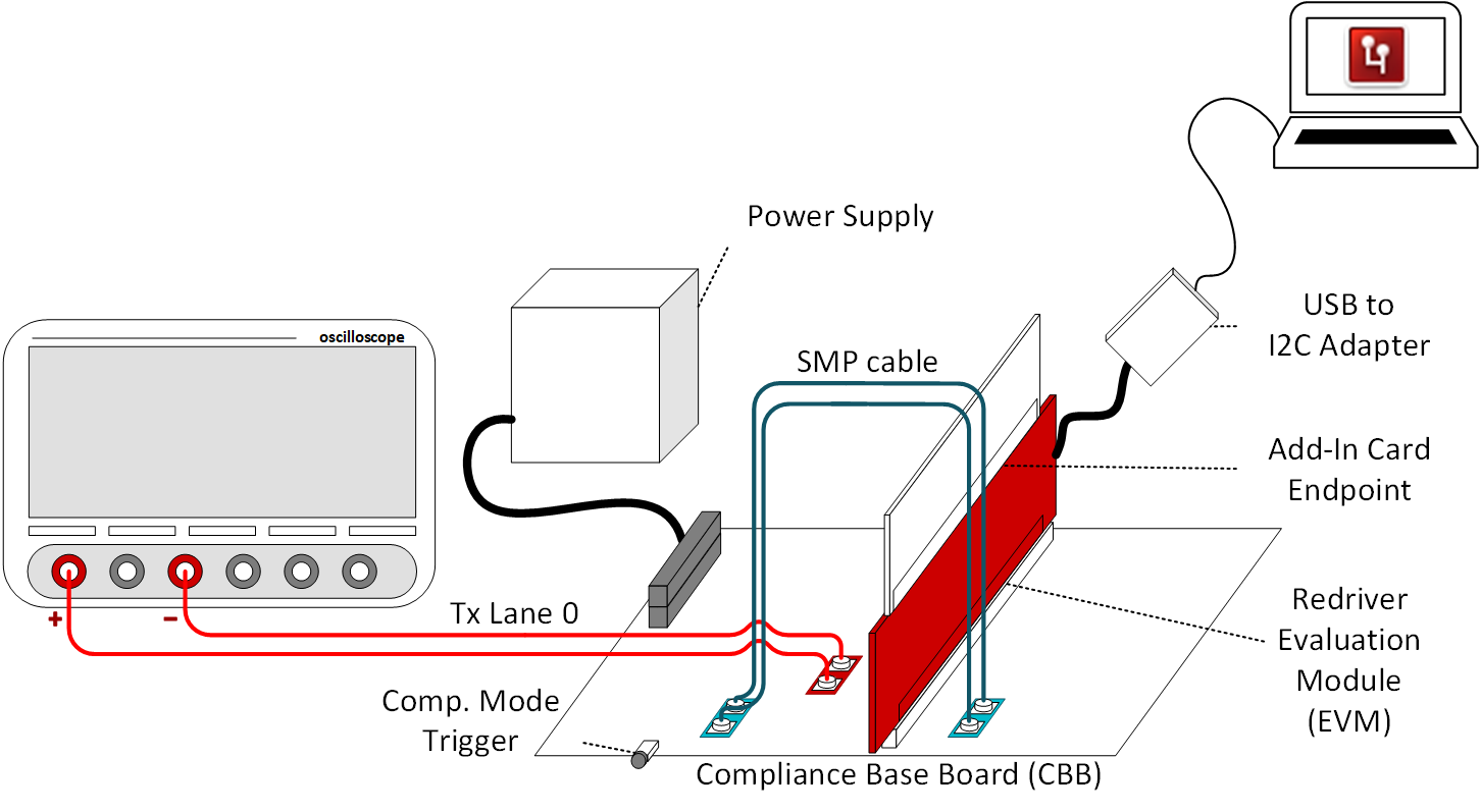
This section focuses on the specifics of Eye Scan during PCIe compliance. A typical PCIe TX compliance setup is visualized in Figure 4-1 using a Texas Instruments PCIe Gen5.0 redriver evaluation module (EVM) and a PCIe Gen5.0 capable Add-in-Card (AIC) endpoint to conduct testing and Eye Scan captures.

Figure 4-1 PCIe TX Compliance Setup
During PCIe compliance testing, Eye Scan can be used to observe vertical eye quality at the redriver’s transmitter. Through I2C programming, the redriver’s EQ boost settings can subsequently be changed to adjust the boost applied at the redriver transmitter, which can assist in the redriver tuning process. For the redriver EQ boost setting selected, the Eye Scan algorithm is run and the resulting plot captured to understand if the PCIe channel is well-equalized,over-equalized, or under-equalized. Please note that in a typical PCIe compliance setup, minimal post-channel insertion loss is present. Thus, the Eye Scan capture more accurately represents the vertical eye seen at the receiver of the oscilloscope or post-processing software.
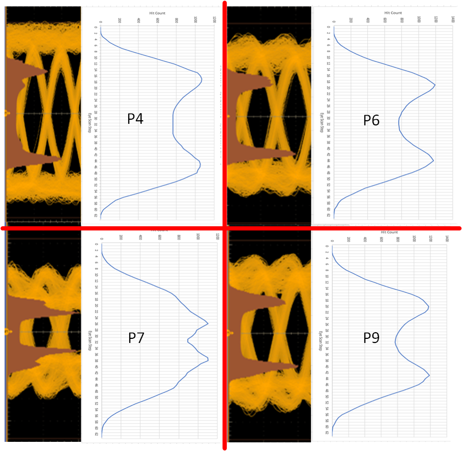
Understanding the effects of PCIe TX Presets on vertical eye quality is critical due to potential impact on channel performance and signal integrity. Eye Scan can easily capture the effects of PCIe TX Presets during compliance testing. As shown in Figure 4-2, the effects of preshoot and de-emphasis for Presets P5, P6, and P9 can be realized using Eye Scan captures and plots in comparison to oscilloscope captures. In each of the Preset captures, the EQ boost settings of the redriver are held constant. For reference, the PCIe TX Preset table for P4, P6, P7, and P9 is included in Table 4-1.
| TX Preset | Preshoot (dB) | De-emphasis (dB) |
|---|---|---|
| P4 | 0 | 0 |
| P6 | 2.5 ± 1 | 0 |
| P7 | 3.5 ± 1 | -6 ± 1.5 |
| P9 | 3.5 ± 1 | 0 |

Figure 4-2 PCIe TX Preset Comparison From Oscilloscope and Eye Scan. From Top Left to Bottom Right: TX Preset P4, P6, P7, P9
As shown in Figure 4-2, Preset P4 applies no preshoot or de-emphasis, resulting in a relatively clean Eye Scan vertical eye capture and a wide flat region between hit count peaks. However, when preshoot is applied to the PCIe signal traveling through the redriver, these added emphases impact the high-frequency components of the signal, resulting in slightly altered Eye Scan vertical eye captures. The effects of preshoot are seen in Presets P6 and P9; preshoot, which applies boost just before the preceding edge of any waveform transitions, decreases the width between the hit count peaks of the Eye Scan plots. Conversely, the effects of de-emphasis is seen in Preset P7; de-emphasis, which applies boost just after waveform transitions, creates a ripple effect during the transitions between the hit count peaks of the Eye Scan plots.