SNVA964 June 2020 LP8866-Q1
1.3 CISPR 25 Measurement Results
The electromagnetic emission measurements are performed on the reference board in accordance with CISPR 25: 2016. All test setup and test procedure comply with the CISPR 25 specification.
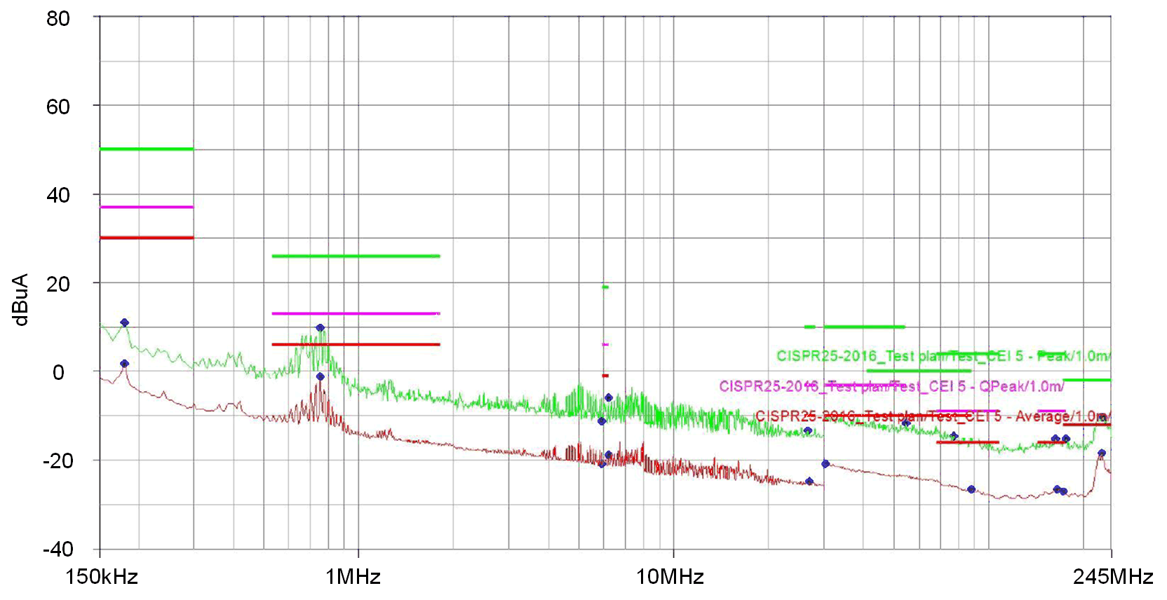
Figure 4 shows the conducted emissions measurement results in the frequency range of 150 kHz to 245 MHz. Current probe method is used. The emissions are measured with the probe positioned 50 mm and 750 mm from the Equipment Under Test (EUT). Here we only provide the results at 50 mm position. Green lines represent the CISPR 25: 2016 Class 5 peak limits and measurement results. Red lines represent the CISPR 25: 2016 Class 5 average limits and measurement results. Measurement with quasi-peak detector is not performed.
 Figure 4. CISPR 25 Class 5 Conducted Emission Limits And Measurement Results
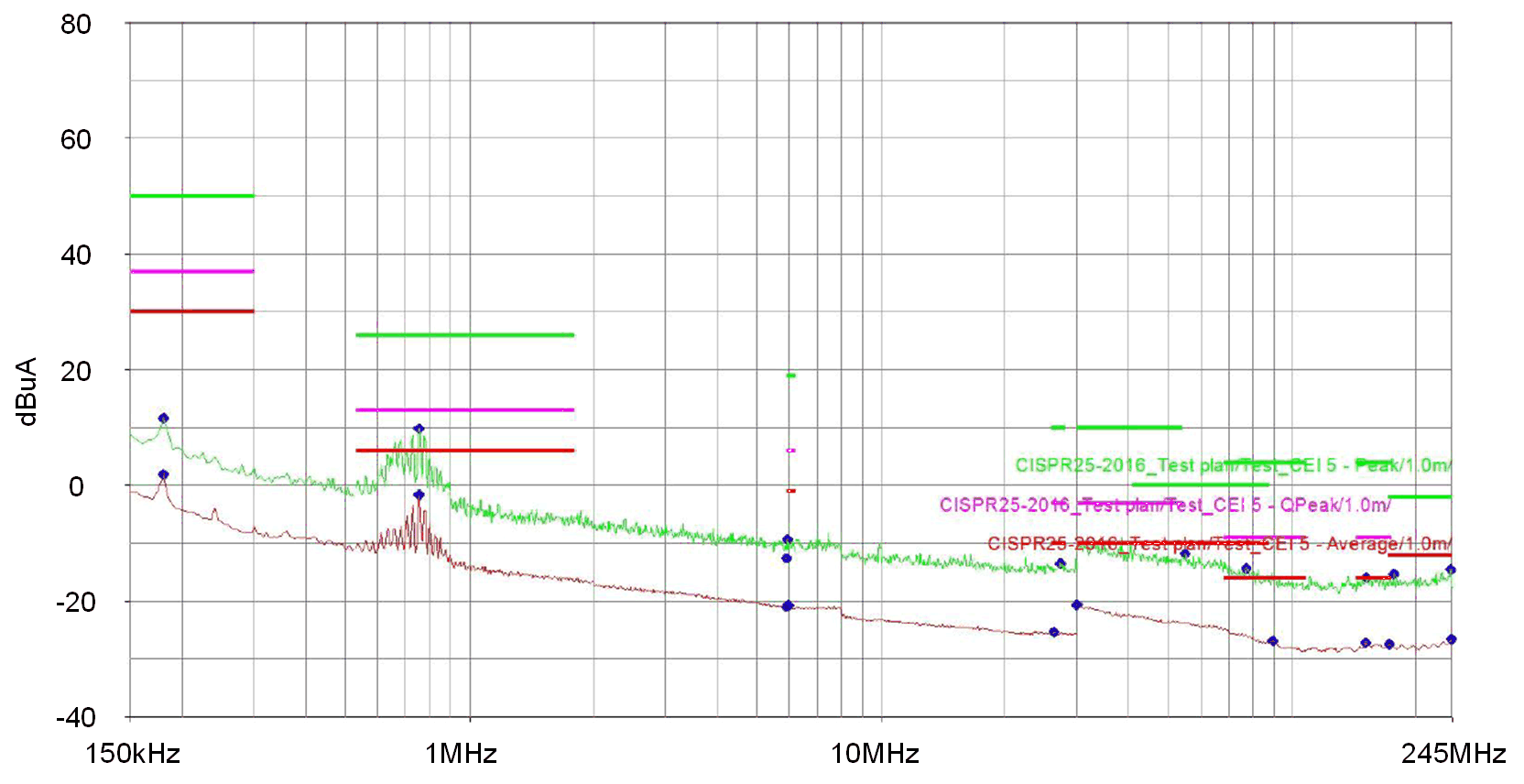
 The ambient noise level of conducted emissions is measured, as shown in Figure 5. The ambient noise requirement can be met. Note that the disturbances in frequency range from 500 kHz to 900 kHz come from the effect of the ambient noise and it may vary sometimes. So it could be ignored during the following comparisons.
 Figure 5. CISPR 25 Class 5 Conducted Emission Limits And Ambient Noise
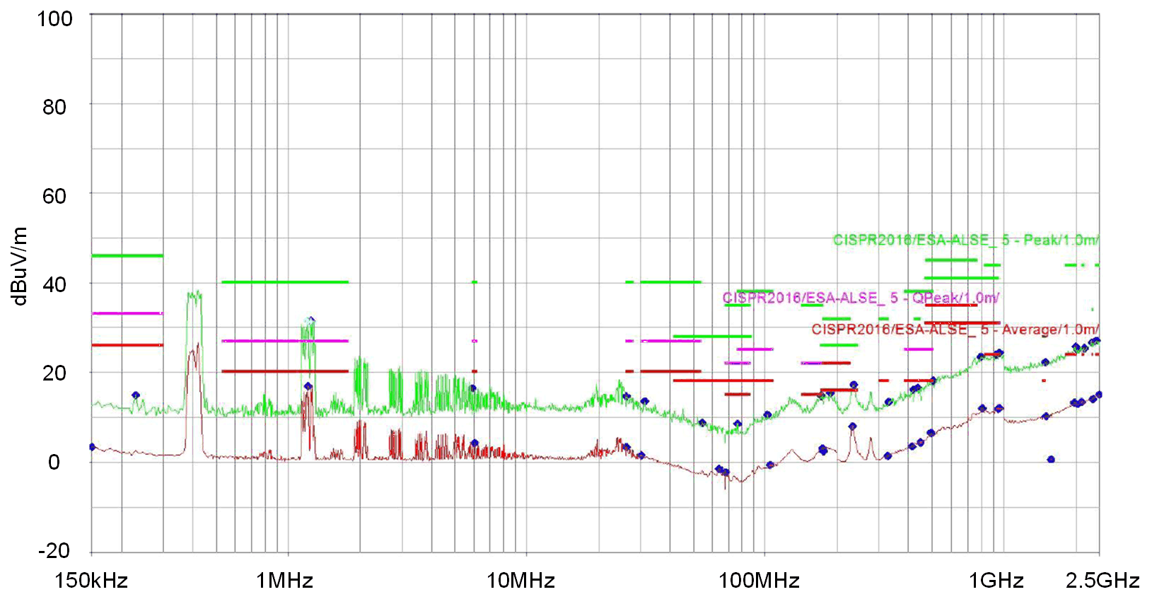
 Figure 6 shows the radiated emissions measurement results in the frequency range of 150 kHz to 2.5 GHz. Absorber-lined shielded enclosure (ALSE) method is used. Only vertical polarization measurement results are shown in this application report.
 Figure 6. CISPR 25 Class 5 Radiated Emission Limits And Measurement Results
 Results show that both conducted and radiated emissions measurement results are below the class 5 peak and average limits, which is the most stringent level. It’s suggested to follow the schematic and layout of the reference design in order to pass the EMI test. Deviation from this design and its effect are analyzed in Section 2.