SNVA988 August 2020 – MONTH LMZM33603 , TPSM265R1 , TPSM53603
2 Efficiency and PCB Solution Size Comparison
Efficiency Comparison of Converter (LMR33630) vs. Power Module (TPSM53603)
Datapoints from each device's data sheet efficiency curves were used to generate the following comparison graphs.
 |
|---|
 |
Efficiency Comparison of Converter (LMR23630) vs. Power Module (LMZM33603)
 |
|---|
 |
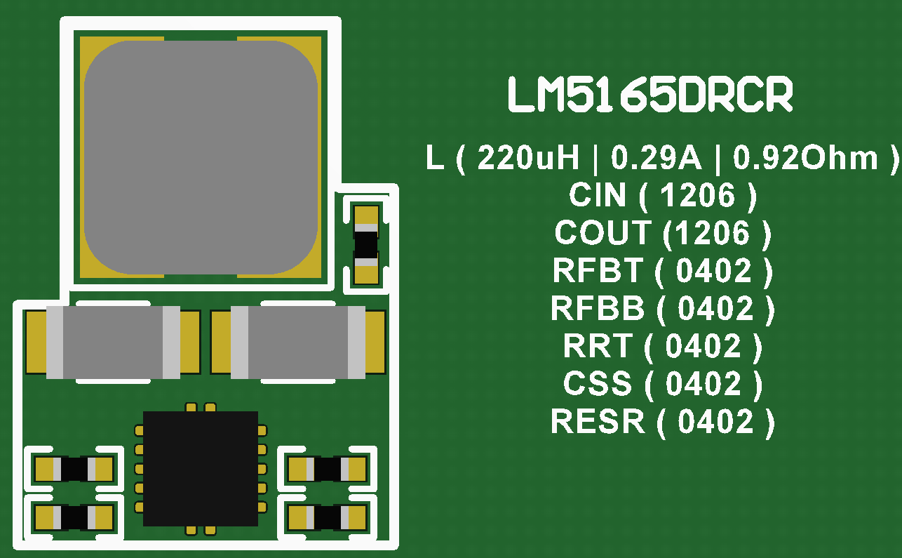
Efficiency Comparison of Converter (LM5165) vs. Power Module (TPSM265R1)
 |
|---|
 |
The power module has an internal inductor that is selected to account for stability and full current loading across the output voltage range following datasheet specification. Though it simplifies the power design and eliminates the need for customers to select a power inductor, when compared to a converter, generally the power module will have a less optimized design. In some cases, like the TPSM53604 module, the power module can have similar efficiency performance as the converter. Often the power module is tailored for typical output voltage rails.
PCB Solution Size Comparison
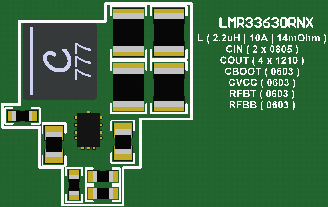
Component selection for both converter and power module PCB solution was selected based on the datasheet recommendation and EVM bill-of-material.
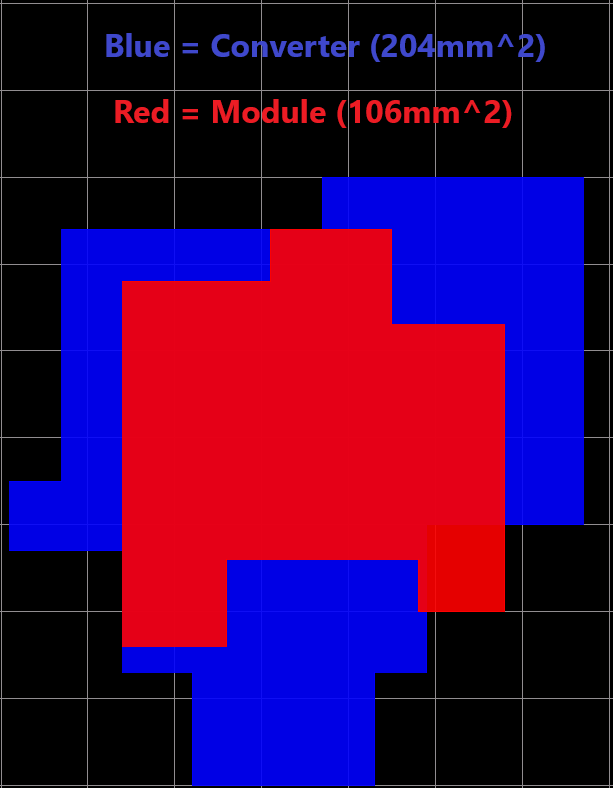
| LMR33630 PCB Solution Size | PCB Overlay Comparison | TPSM53603 PCB Solution Size |
|---|---|---|
 |
 |
 |
The total solution size of the LMR33630 converter circuit was measured to be roughly 204 mm2 compared to 106 mm2 of the TPSM53603 module circuit.
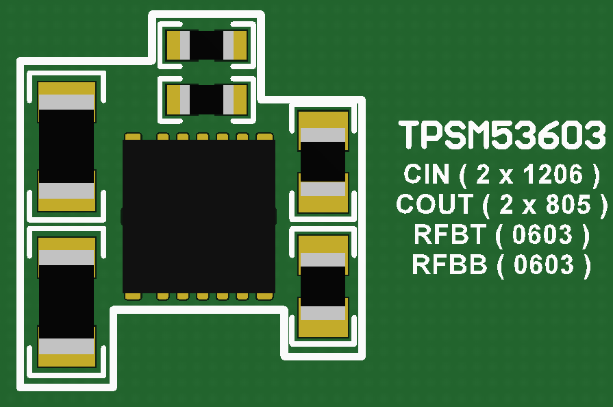
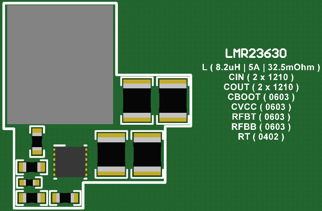
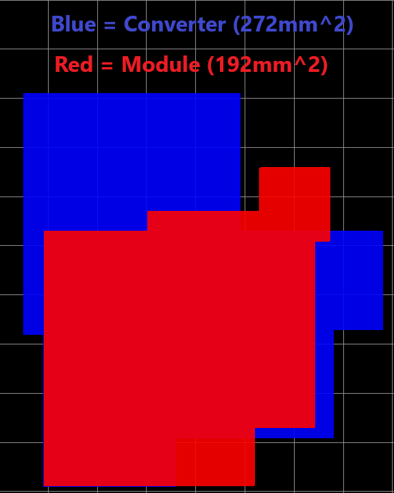
| LMR23630 PCB Solution Size | PCB Overlay Comparison | LMZM33603 PCB Solution Size |
|---|---|---|
 |
 |
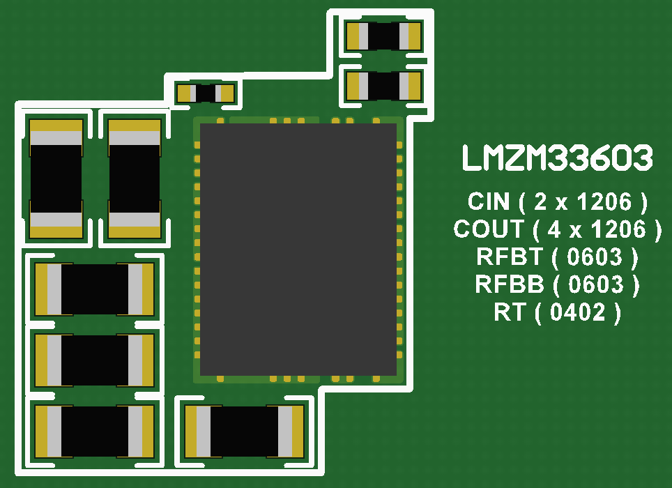 |
The total solution size of the LMR23630 converter circuit was measured to be roughly 272 mm2 compared to 192 mm2 of the LMZM33603 module circuit.
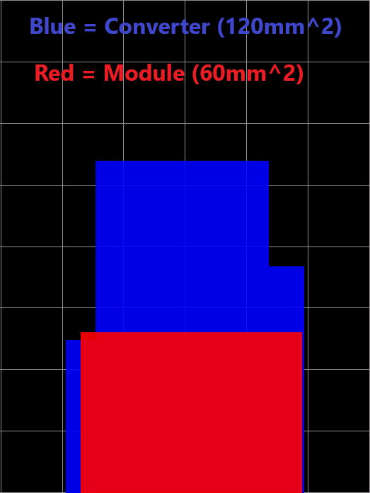
| LMR5165 PCB Solution Size | PCB Overlay Comparison | TPSM265R1 PCB Solution Size |
|---|---|---|
 |
 |
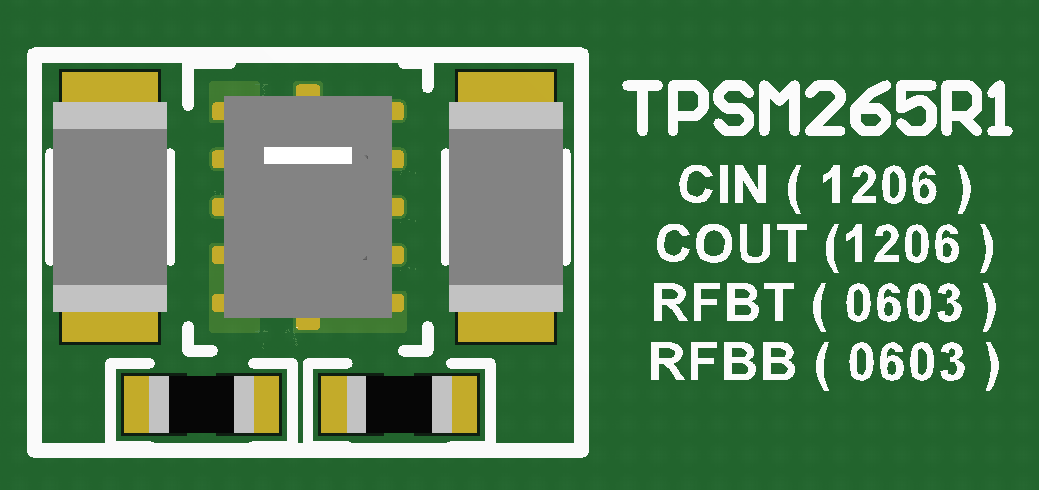 |
The total solution size of the LMR5165 converter circuit was measured to be roughly 120 mm2 compared to 60 mm2 of the TPSM265R1 module circuit.
In most cases, using the power module will provide a smaller solution size compared to the converter. This is especially true for power modules that use 3D packaging where the inductor is over the integrated switching converter and passive components. In this package technology, the majority of the solution size is attributed to the size of the inductor. Power modules that implement side-by-side construction technology will have the inductor designed next to the integrated switching converter. Depending on the required output capacitance to keep the converter stable, power modules with side-by-side construction technology can either be smaller or close to the same solution size as the converter alternative.