SNVAA42 April 2022 LMR33620 , LP5907 , TLV702 , TPS3840 , TPS62260 , TPS65000
2.3 Integrated Power with Camera Module PMIC
TI offers PMICs intended for 3.3 V, 5 V and 12 V camera applications. The TPS65000 family covers 3.3 V and 5 V input applications, while the TPS650330 family covers 5 V and 12 V input applications. Both of these solutions have the capability to meet power up and power down sequencing requirements. The TPS65000x devices have EN pins for each regulator that can be sequenced similar to the discrete approach discussed in Section 2.1 and Section 2.2. The TPS65033x devices control the power sequence through internal register settings and Non-Volatile Memory (NVM). The engineer can program a custom power sequence or use an existing part number compatible with specific image sensors. Refer to the Camera PMIC Spin Selection Guide for current options.
The TPS650330-Q1 device powers up according to the default power sequence register settings. The default power down sequence can be configured in the reverse order of the power up sequence, or it can be configured to meet the imager and/or serializer power down sequence requirements. To initiate a controlled power down sequence via I2C communication, unlock the device control registers and set the PWR_ON bit to 0. Input power must remain present throughout the shutdown to maintain the desired power down sequence.
| Write Transaction | Device Address (7-bit) | Register Address | Write Data |
|---|---|---|---|
| 1 | 0x60 | 0x02 | 0xDD |
| 2 | 0x60 | 0x05 | PWR_ON = ‘0’ |
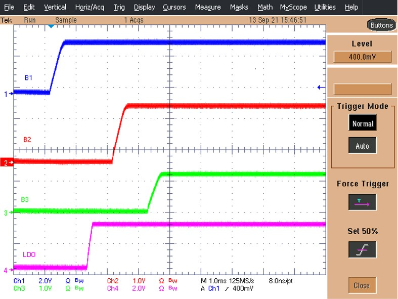
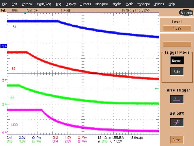
This is demonstrated using the PMIC-Serializer base-board in reference designs TIDA-050035 and TIDA-050036. The default power sequence settings are re-programmed to match the typical image requirements from Figure 2-1 and Figure 2-2 The power up sequence in Figure 2-4 is achieved by ramping the Power Over Coax (POC) input voltage. The power down sequence in Figure 2-5 is achieved by executing the I2C transactions described in Table 2-1 via the FPD-Link III SERDES back-channel.
The fully integrated automotive camera PMIC, TPS650330-Q1, meets strict power up and power down sequence requirements through internal register settings, removing the need for external supervisors and PCB routing. This solution optimizes size, performance, and cost of the camera module.
 Figure 2-4 TPS650330-Q1 Programmable Power Up Sequence
 Figure 2-5 TPS650330-Q1 Programmable Power Down Sequence