SPRAD59 October 2023 TMS320F280039
4 Bit Timing Configuration
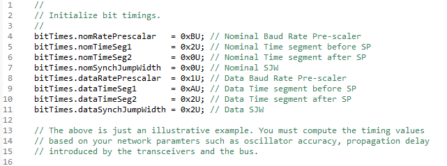
Bit timing configuration differs between classic CAN and CAN FD. The process is relatively easier in classic CAN, since the bit-rate is the same for the entire frame. However, in CAN FD, two different bit-rates can be used: a slower “nominal” bit-rate and a faster “data” bit-rate. In the MCAN module, these two bit-rates are configured by writing to the MCAN_NBTP and MCAN_DBTP registers respectively during the module initialization. Note that an application can choose to only take advantage of the higher number of data bytes per frame that can be transmitted in CAN FD and use the same bit-rate for the entire frame. The faster bit-rate for the data phase also warrants Transmitter Delay Compensation (TDC) without which bit errors can occur. Below is an example for calculating bit-timing parameters:
Example 1
Assume the following parameters are desired with a CAN module clock of 200 MHz:
Nominal bit-rate = 500kbps, Data bit-rate = 2Mbps.
The formula for computing the bit-rate is given by:
For a nominal bit-rate of 500kbps, the product of Bit-rate prescaler x Bit-time must be equal to 400. This can be achieved with multiple combinations of the prescaler and bit-time, as long as the rules laid out by the CAN protocol are not violated. For example, a prescaler of 20 and a bit-time of 20 TQ can be chosen. A prescaler of 20 (NBRPreg = 19) yields a bit-clock of 10 MHz with a resultant time-quanta (TQ) of 100 ns. A bit-time of 20 TQ can be achieved with multiple combinations for TSEG1 and TSEG2 resulting in varying sample-points (SP).
Bit-time = (NTSEG1reg + 1) + (NTSEG2reg + 1) + 1, where NTSEG1reg and NTSEG2reg represent the actual values written into MCAN_NBTP.NTSEG1 and MCAN_NBTP.NTSEG2 bit-fields respectively. If TSEG1 is chosen to be 16 (NTSEG1reg = 15) and TSEG2 is chosen to be 4 (NTSEG2reg =3), those values yield a sampling-point of 80%. By adjusting the TSEG1 and TSEG2 values, the sampling-point can be moved within the bit-time based on the network parameters.
Similar calculation is used for data bit-rate of 2Mbps. For a data bit-rate of 2Mbps, the product of Bit-rate prescaler x Bit-time must be equal to 100. This can be achieved with multiple combinations of the prescaler and bit-time, as long as the rules laid out by the CAN protocol are not violated. For example, a prescaler of 5 and a bit-time of 20 TQ can be chosen. A prescaler of 5 (DBRPreg = 4) yields a bit-clock of 40 MHz with a resultant time-quanta (TQ) of 25ns. A bit-time of 20 TQ can be achieved with multiple combinations for TSEG1 and TSEG2 resulting in varying sample-points (SP).
Bit-time = (DTSEG1reg + 1) + (DTSEG2reg + 1) + 1, where DTSEG1reg and DTSEG1reg represent the actual values written into MCAN_DBTP.DTSEG1 and MCAN_DBTP.DTSEG2 bit-fields respectively. If TSEG1 is chosen to be 16 (DTSEG1reg = 15) and TSEG2 is chosen to be 4 (NTSEG2reg =3), those values yield a sampling-point of 80%. By adjusting the TSEG1 and TSEG2 values, the sampling-point can be moved within the bit-time based on the network parameters.
 Figure 4-1 MCAN Bit-timing Configuration