SPRAD59 October 2023 TMS320F280039
7.3 MCAN Transmit Concepts
This section outlines the additional features in MCAN.
- Each Tx Message can be configured to transmit in Classic CAN or CAN-FD mode
- Transmit Pause
- Transmit Cancellation
- Tx FIFO / Tx Queue
Within the Message RAM, the Tx Buffer space can have the following possible configurations:
- Only Tx Buffers
- Tx Buffers + Tx FIFO
- Tx Buffers + Tx Queue
| Tx Buffers | Tx Buffers + Tx FIFO | Tx Buffers + Tx Queue |
|---|---|---|
txBufNum = BUFF_SIZE (MCAN_TXBC.NDTB)txFIFOSize = 0 (MCAN_TXBC.TFQS) | txBufNum = BUFF_SIZE (MCAN_TXBC.NDTB)txFIFOSize = FIFO_SIZE (MCAN_TXBC.TFQS)txBufMode = 0 (MCAN_TXBC.TFQM) | txBufNum = BUFF_SIZE (MCAN_TXBC.NDTB)txFIFOSize = QUE_SIZE (MCAN_TXBC.TFQS)txBufMode = 1 (MCAN_TXBC.TFQM) |
The differences in functionality and potential use cases for each of the sections have been specified in Table 7-3 below:
| Feature | Tx Buffers | Tx FIFO | Tx Queue |
|---|---|---|---|
| Information directly available to host (CPU) | Buffer Element number is known. | Only Put and Get indices can be read from a register (MCAN_TXFQS) | Only Put and Get indices can be read from a register (MCAN_TXFQS) |
| Element transmitted first | Element with lowest message ID | Oldest Element | Element with lowest message ID |
| Put Index / Get Index | Not applicable | Put index points to where the most recent frame is stored. Incremented with Add Transmit Request.Get index points to the oldest element, which is be transmitted next. | Put index points to the lowest, free buffer element (within the queue), where the most recent frame is stored. Updated with Add Transmit Request. Get index is always Zero |
| Transmission of multiple messages with same ID | Element with lowest buffer number is transmitted | Oldest Element is transmitted | Element with lowest buffer number is transmitted |
| Full Condition | Not applicable | In case FIFO is full, no message can be written unless a requested transmission is completed | In case queue is full, no message can be written unless a requested transmission is completed |
| Tx Cancellation | Possible | Not Possible | Not Possible |
| Use Cases | Advantage is that the application knows which message ID is stored in which buffer element and hence, can be edited before sending | Applications where frames have to be transmitted in a specific order, not following increasing order of message IDs | Advantage is that buffer number is automatically handled by the Put index. Application need not track which buffer is empty based on the message ID priority |
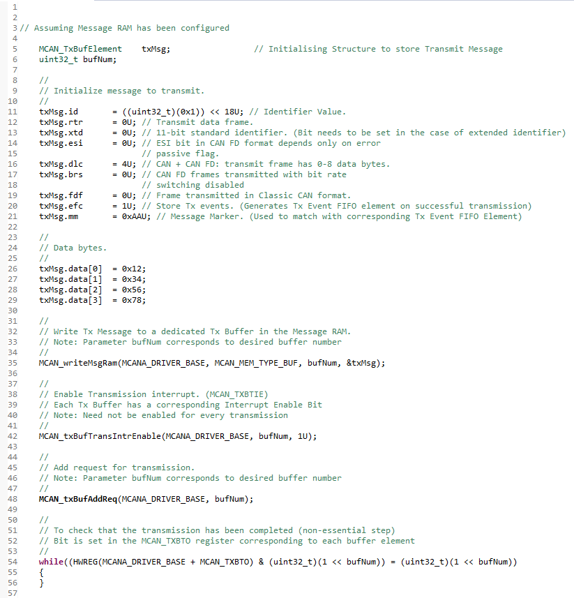
 Figure 7-2 Transmission with MCAN