SPRUJ87 june 2023
2.7 System Power
The BP-AM2BLDCSERVO power tree is divided between motor axis-1, motor axis-2 and common digital and analog supplies. 24 V DC power is provided through the J5 and J6 screw-terminals. After passing through over-voltage/reverse-polarity protections, this supply is used to directly power the BLDC motor drivers and encoder/resolver on-board regulators.
When motor bench power is applied to the J5 and J6 terminal blocks, the U2/U3 over-voltage and reverse polarity circuits are powered. J5 and J6 can be powered from the same bench source or different bench sources, allowing for different motor voltages to be used on each axis.
In normal condition, the J5/J6 bench power will power the BLDC motor drivers and the Encoder/Resolver regulators. In an over-voltage or reverse polarity state, the LM74502 NFET switch path remains in a high impedance state, protecting the downstream devices. Over-voltage protection disables the power to the system if J5/J6 exceeded. Reverse polarity protection disables the power to the system if the J5/J6 negative voltage terminal exceeds the positive voltage terminal.
Motor and Encoder Bench Power
After bench supply power-on through J5/J6, the encoder/resolver connectors are initially disconnected from their regulator by way of the U5/U40 load switches. This prevents typical high inrush currents from attached encoders/resolvers from effecting regulator power-on and feedback loop stabilization. GPIO control from the attached LaunchPad is required to enable the U5/U40 load switches and power on the attached encoders/resolves.
 Figure 2-15 Motor Axis-1 Power
Distribution
 Figure 2-16 Motor Axis-2 Power
Distribution
Figure 2-16 Motor Axis-2 Power
DistributionSystem Digital/Analog Power
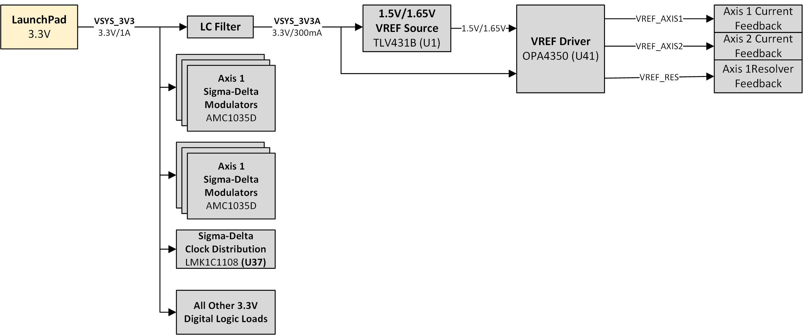
The LaunchPad 3.3V/1A supply is used to power all of the BP-AM2BLDCSERVO 3.3V logic and analog loads. See the below diagram of the 3.3V derived power tree. VSYS_3V3 power is applied from the attached LaunchPad pins as soon as the LaunchPad is powered on.
This powers on all of the 3.3V powered digital loads such as the AMC1035 Sigma-Delta modulators, the sigma-delta clock distribution components. Through an LC filter, the also power on the onboard VREF sources, and current sense paths making all of these components ready to send SDFM/current sense data back to the attached MCU.
 Figure 2-17 Common 3.3V Digital and Analog
Power Tree