SPRUJ87 june 2023
2.5 Jumper Information
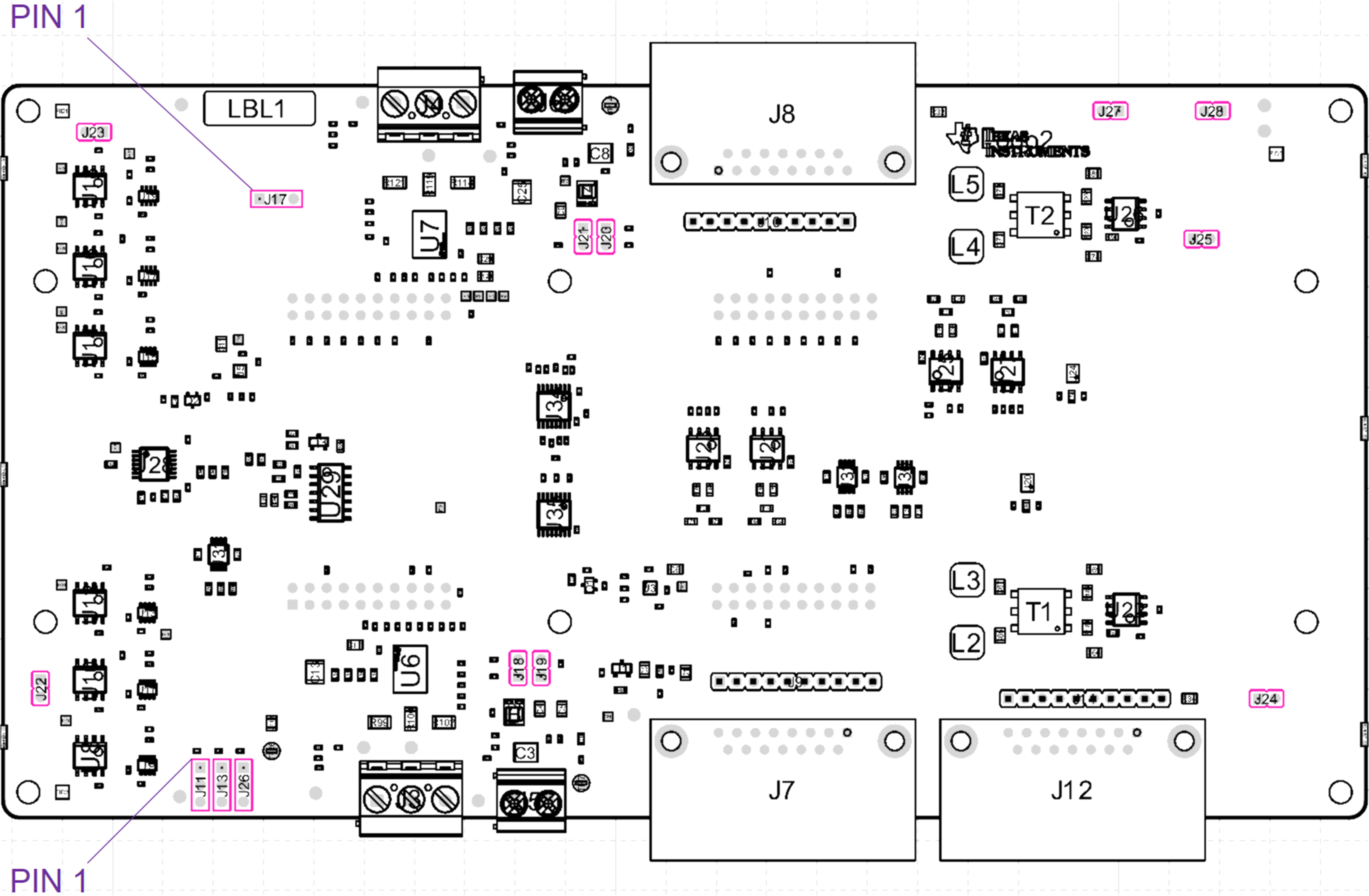
This section describes the jumper selectable options on this board. See table and figures below for list of available jumper options, details and configuration defaults. Additional jumper details are located in each the major
 Figure 2-6 Layout Top View - Jumper
Locations
Figure 2-6 Layout Top View - Jumper
Locations| Axis | Jumper | Function |
Default LP-AM243x Configuration |
Default LP-AM263x Configuration |
|---|---|---|---|---|
| Both | J11 |
VSENSE/ISENSE Select Jumper pins 1-2 shorted: Select Axis-1, Phase-A INA241 current sense output routed to BoosterPack J15.24 Jumper pins 2-3 shorted: Select Axis-2 DRV8316 VSENSE Phase-A Output routed to BoosterPack J15.24 |
Jumper installed across pins 2-3 Routes optional motor VSENSE into GPADC input |
Jumper installed across pins 1-2 Routes required motor ISENSE into SAR ADC input |
| J13 |
VSENSE/ISENSE Select Jumper pins 1-2 shorted: Select Axis-1, Phase-B INA241 current sense output routed to BoosterPack J15.24 Jumper pins 2-3 shorted: Select Axis-2 DRV8316 VSENSE Phase-B Output routed to BoosterPack J15.24 |
Jumper installed across pins 2-3 Routes optional motor VSENSE into GPADC input |
Jumper installed across pins 1-2 Routes required motor ISENSE into SAR ADC input |
|
| J26 |
VSENSE/ISENSE Select Jumper pins 1-2 shorted: Select Axis-1, Phase-C INA241 current sense output routed to BoosterPack J15.24 Jumper pins 2-3 shorted: Select Axis-2 DRV8316 VSENSE Phase-C Output routed to BoosterPack J15.24 |
Jumper installed across pins 2-3 Routes optional motor VSENSE into GPADC input |
Jumper installed across pins 1-2 Routes required motor ISENSE into SAR ADC input |
|
| J17 |
SDFM Clock Feedback Select Jumper pins 1-2 shorted: Jumper pins 2-3 shorted: asdad |
Jumper Uninstalled Function not used |
||
| J27/J28 |
Encoder/SDFM MUX Select J27/J28 uninstalled: selects AM243x SDFM and Encoder Paths J27/J28 installed: selects AM263x SDFM and Encoder Paths |
J27 uninstalled | J27 Installed | |
| Axis-1 | J18/J19 |
Encoder/Resolver Voltage Select J18 installed: sets VSENSOR1 to 12 V J19 installed: sets VSENSOR1 to 5.0V Note: only one jumper must be installed at a time during operation. |
J19 Installed This defaults VSENSOR1 to 5.0V compatible with most absolute encoders. |
J19 Installed This defaults VSENSOR1 to 5.0V compatible with most absolute encoders. |
| J22 |
SDFM Manchester Encoding Select Uninstalled: Manchester encoding disabled Installed: Manchester encoding enabled |
J22 uninstalled | J22 uninstalled | |
| J24 |
RS485 Absolute Encoder 2-Wire/4-Wire MUX Select Uninstalled: RS-484 4-Wire Path Selected Installed: RS-485 2-Wire Path Selected |
J24 uninstalled Compatible with Heidenhain EnDat22 Encoders |
J24 uninstalled Compatible with Heidenhain EnDat22 Encoders |
|
| Axis-2 | J20/J21 |
Encoder/Resolver Voltage Select J20 installed: sets VSENSOR2 to 12 V J21 installed: sets VSENSOR2 to 5.0V Note: only one jumper must be installed at a time during operation. |
J21 Installed This defaults VSENSOR2 to 5.0V compatible with most absolute encoders. |
J21 Installed This defaults VSENSOR2 to 5.0V compatible with most absolute encoders. |
AM243x/AM263x ISENSE/VSENSE Select
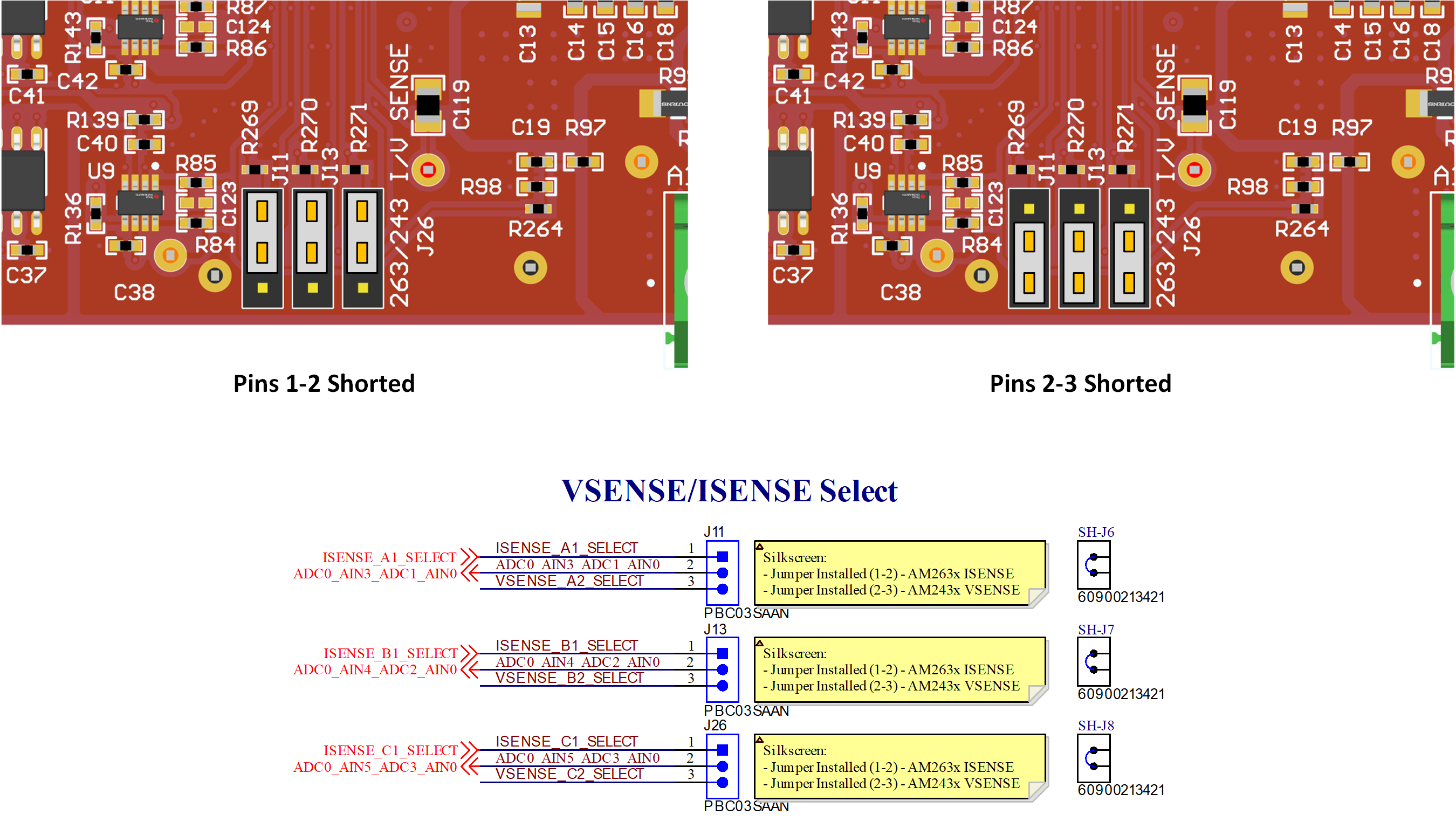
The below diagrams describe the select path used to choose between Axis-1 in-phase current sense and Axis-2 voltage sense into a set of LaunchPad ADC channels. The Axis-1 in-phase current sense path is only usable with the AM263x LaunchPad SAR ADC channels.
 Figure 2-7 Axis-1 ISENSE/VSENSE Select -
Jumper J11, J13, and J26 Configuration
 Figure 2-8 Axis-1 ISENSE/VSENSE Select -
Layout/Schematic Excerpt for Jumper J11, J13, and J26
Figure 2-8 Axis-1 ISENSE/VSENSE Select -
Layout/Schematic Excerpt for Jumper J11, J13, and J26AM243x/AM263x PRU Encoder/Sigma-Delta MUX
The below diagrams describe the MUX path used to de-MUX and MUX a set of overlapping but conflicting pins to the AM2x MCU AM243x and AM263x LaunchPad. Select lines for these MUX paths are either jumper selectable.
 Figure 2-9 PRU SDFM/Absolute Encoder MUX
– Jumper J27 and J28 Configurable
Figure 2-9 PRU SDFM/Absolute Encoder MUX
– Jumper J27 and J28 ConfigurablePRU Sigma-Delta Modulator Clock Path Select
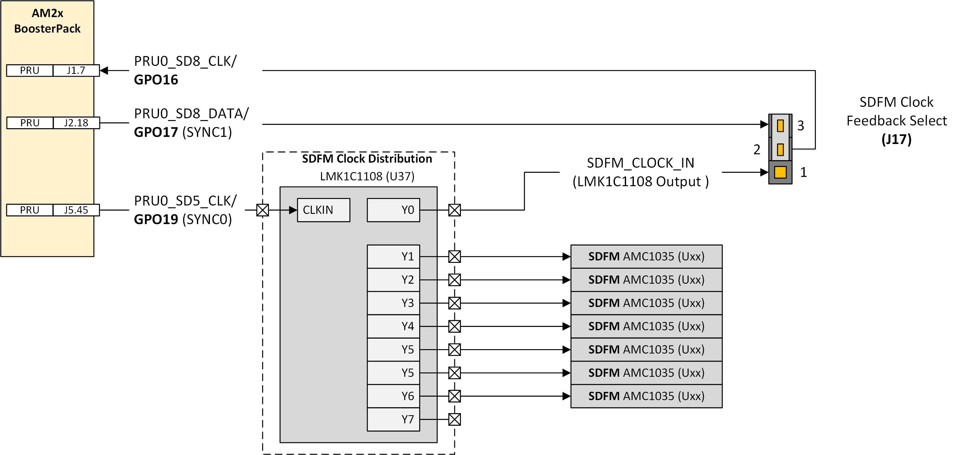
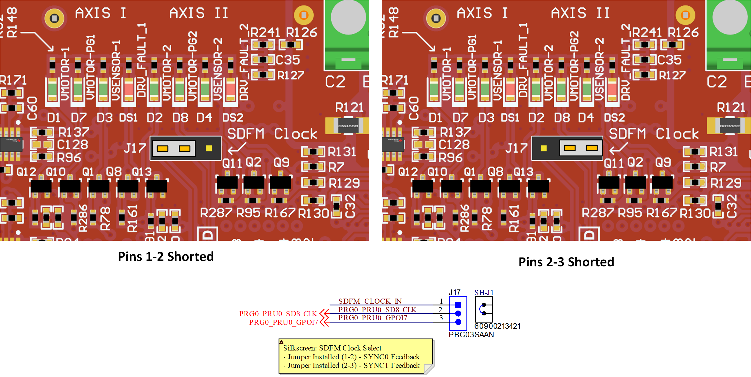
The below diagrams describe the select path used to choose between the different PRU Sigma-Delta Modulator (SDFM) feedback clocks. The SYNC0 and SYNC1 paths from the PRU are used to generate two different clocks that can be used for both clocking data out of the attached SDFM AM1035 transceivers as well as clocking data into the AM2x MCU.
 Figure 2-10 PRU Sigma-Delta Modulator
Clock Path Select – J17
 Figure 2-11 BP-AM2BLDCSERVO Layout -
Layout/Schematic Excerpt for PRU SDFM Clock Path Select – J17