SWRA647A January 2019 – September 2020 CC3130 , CC3135
5.4 UART Hardware Connection Using the FTDI Emulation Board
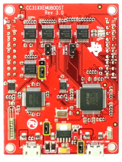
The CC31XXEMUBOOST can provide the required USB to UART/GPIO interface for programming the serial flash through Uniflash. The PC drivers for this board are included in the installation of Uniflash. The CC31XXEMUBOOST is connected through USB from socket J6 to the PC. The jumpers on the CC31XXEMUBOOST should be connected as shown in Figure 5-1.
 Figure 5-1 CC31XXEMUBOOST Jumpers
The CC31XXEMUBOOST uses a logic level of 3.3 V by default, but there are level shifters on the CC31XXEMUBOOST, and it can be powered in-dependently with a different I/O voltage by removing the jumper from J4, and applying the external power to pin 1 of jumper J4. On the product being programmed, the relevant CC313x pins must be brought out for physical contact with the programmer (such as male headers or test pads), and must be driven by no other source while programming. The HIB pin on the CC31XXEMUBOOST is temporarily pulled to GND by the Uniflash utility at the beginning of the flashing procedure, which is necessary to synchronize the device and the PC software. The CC31XXEMUBOOST is configured to receive commands from the Uniflash program for toggling its HIB pin at the appropriate times during the programming process.
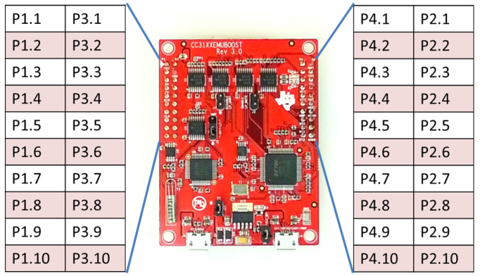
 Figure 5-2 Pin Map
 Figure 5-3 Programming Through USB