SWRA647A January 2019 – September 2020 CC3130 , CC3135
4 Programming Directly Through SPI
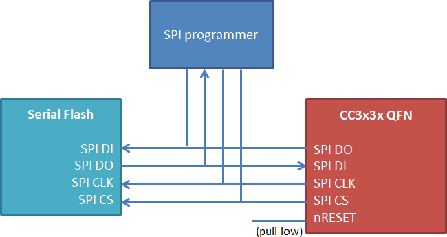
The serial flash device is programmed directly, starting at memory offset 0, with one of the gang image files created by Uniflash: either Programming.bin or Programming.hex, depending on the SPI programmer. The serial flash may be programmed after board assembly, provided some schematic and layout considerations are taken:
- The serial flash SPI interface pins must be brought out for physical contact with the programmer (such as headers or test pads).
- The SPI lines must not be driven by any other source while programming.
- The CC313x device is held in reset during programming to prevent I/O contention.
 Figure 4-1 Programming Through SPI